ACPL-C784 Overview
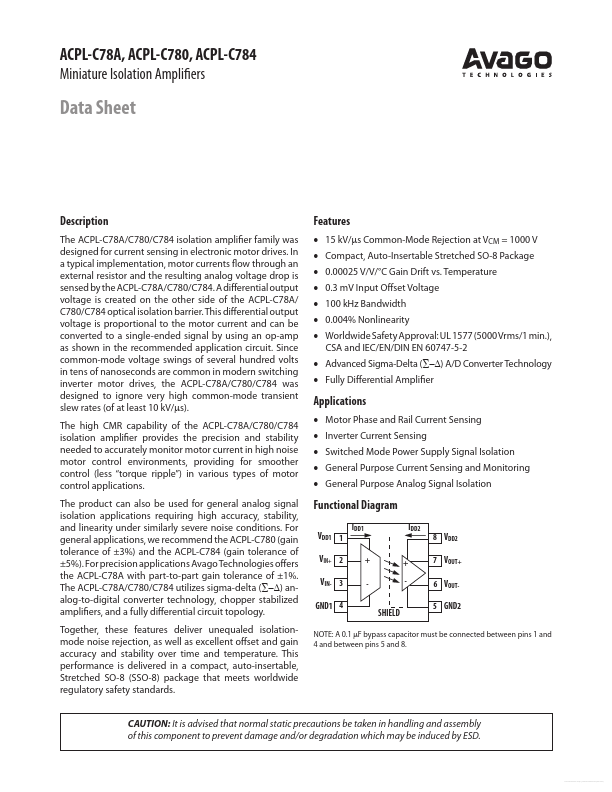
The ACPL-C78A/C780/C784 isolation amplifier family was designed for current sensing in electronic motor drives. In a typical implementation, motor currents flow through an external resistor and the resulting analog voltage drop is sensed by the ACPL-C78A/C780/C784. A differential output voltage is created on the other side of the ACPL-C78A/ C780/C784 optical isolation barrier.
ACPL-C784 Key Features
- 15 kV/µs mon-Mode Rejection at VCM = 1000 V
- pact, Auto-Insertable Stretched SO-8 Package
- 0.00025 V/V/°C Gain Drift vs. Temperature
- 0.3 mV Input Offset Voltage
- 100 kHz Bandwidth
- 0.004% Nonlinearity
- Advanced Sigma-Delta (∑-∆) A/D Converter Technology
- Fully Differential Amplifier