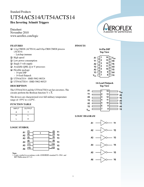
Datasheet4U Logo Datasheet4U.com

UT54ACTS14 - Hex Inverting Schmitt Triggers

Download the UT54ACTS14 datasheet PDF. This datasheet also covers the UT54ACS14 variant, as both devices belong to the same hex inverting schmitt triggers family and are provided as variant models within a single manufacturer datasheet.

General Description

The UT54ACS14 and the UT54ACTS14 are hex inverters.

The circuits perform the Boolean function Y = A.

The devices are characterized over full military temperature range of -55°C to +125°C.

Key Features

  • ‰ 1.2μ CMOS (ACTS14) and 0.6μ CRH CMOS process (ACS14) - Latchup immune ‰ High speed ‰ Low power consumption ‰ Single 5 volt supply ‰ Available QML Q or V processes ‰ Flexible package - 14-pin DIP - 14-lead flatpack ‰ UT54ACS14 - SMD 5962-96524 ‰ UT54ACTS14 - SMD 5962-96525.

📥 Download Datasheet

Note: The manufacturer provides a single datasheet file (UT54ACS14-AeroflexCircuitTechnology.pdf) that lists specifications for multiple related part numbers.

Datasheet Details

Part number UT54ACTS14
Manufacturer Aeroflex Circuit Technology
File Size 221.39 KB
Description Hex Inverting Schmitt Triggers
Datasheet download datasheet UT54ACTS14 Datasheet

Full PDF Text Transcription (Reference)

The following content is an automatically extracted verbatim text from the original manufacturer datasheet and is provided for reference purposes only.

View original datasheet text
Standard Products UT54ACS14/UT54ACTS14 Hex Inverting Schmitt Triggers Datasheet November 2010 www.aeroflex.com/logic FEATURES ‰ 1.2μ CMOS (ACTS14) and 0.6μ CRH CMOS process (ACS14) - Latchup immune ‰ High speed ‰ Low power consumption ‰ Single 5 volt supply ‰ Available QML Q or V processes ‰ Flexible package - 14-pin DIP - 14-lead flatpack ‰ UT54ACS14 - SMD 5962-96524 ‰ UT54ACTS14 - SMD 5962-96525 DESCRIPTION The UT54ACS14 and the UT54ACTS14 are hex inverters. The circuits perform the Boolean function Y = A. The devices are characterized over full military temperature range of -55°C to +125°C. FUNCTION TABLE INPUT A H L OUTPUT Y L H LOGIC SYMBOL (1) A1 (3) A2 A3 (5) A4 (9) A5 (11) A6 (13) 1 (2) Y1 (4) Y2 (6) Y3 (8) Y4 (10) Y5 (12) Y6 Note: 1.