3933 Overview
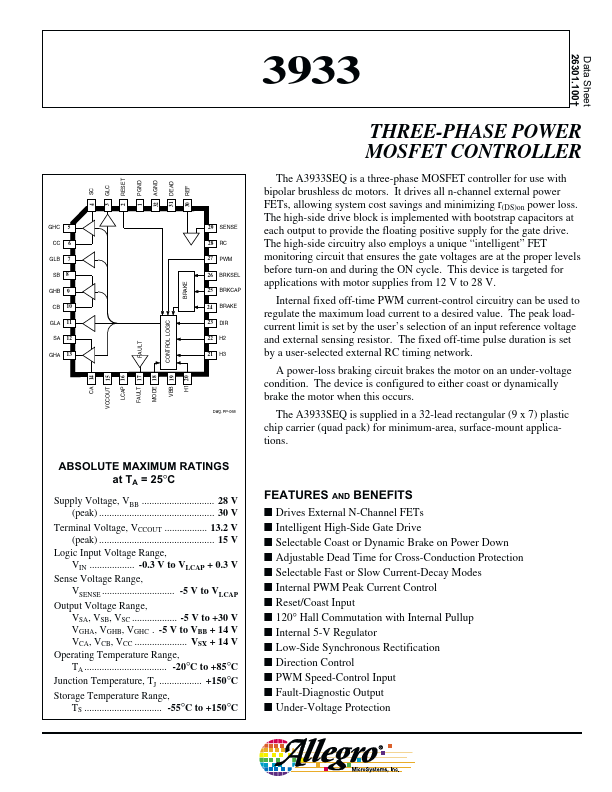
Data Sheet 26301.100† 3933 RESET PGND AGND GLC DEAD REF SC THREE-PHASE POWER MOSFET CONTROLLER The A3933SEQ is a three-phase MOSFET controller for use with bipolar brushless dc motors. It drives all n-channel external power FETs, allowing system cost savings and minimizing r(DS)on power loss. The high-side drive block is implemented with bootstrap capacitors at each output to provide the floating positive supply for...