ADP1110
ADP1110 is Step-Up/Step-Down Switching Regulator manufactured by Analog Devices.
FEATURES
Operates at Supply Voltages From 1.0 V to 30 V Step-Up or Step-Down Mode Minimal External ponents Required Low-Battery Detector User-Adjustable Current Limiting Fixed or Adjustable Output Voltage Versions 8-Pin DIP or SO-8 Package
APPLICATIONS Cellular Telephones Single-Cell to 5 V Converters Laptop and Palmtop puters Pagers Cameras Battery Backup Supplies Portable Instruments Laser Diode Drivers Hand-Held Inventory puters
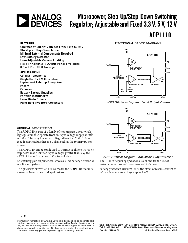
FUNCTIONAL BLOCK DIAGRAMS
A2
VIN GAIN BLOCK/ ERROR AMP
220m V REFERENCE
A1 OSCILLATOR
A0 ILIM SW1
Q1
PARATOR R2 R1 300kΩ
DRIVER
SENSE
SW2
ADP1110 Block Diagram- Fixed Output Version
GENERAL DESCRIPTION
The ADP1110 is part of a family of step-up/step-down switching regulators that operate from an input voltage supply as little as 1.0 V. This very low input voltage allows the ADP1110 to be used in applications that use a single cell as the primary power source.
The ADP1110 can be configured to operate in either step-up or step-down mode, but for input voltages greater than 3 V, the ADP1111 would be a more effective solution.
An auxiliary gain amplifier can serve as a low battery detector or as a linear regulator.
The quiescent current of 300 µA makes the ADP1110 useful in remote or battery powered applications.
A2
VIN GAIN BLOCK/ ERROR AMP
220m V REFERENCE
A1 OSCILLATOR
A0 ILIM SW1 Q1
PARATOR
DRIVER
SW2
ADP1110 Block Diagram- Adjustable Output Version
The 70 k Hz frequency operation also allows for the use of surface-mount external capacitors and inductors.
Battery protection circuitry limits the effect of reverse current to safe levels at reverse voltages up to 1.6 V.
REV. 0
Information furnished by Analog Devices is believed to be accurate and reliable. However, no responsibility is assumed by Analog Devices for its use, nor for any infringements of patents or other rights of third parties which may result from its use. No license is granted by implication or otherwise under any...