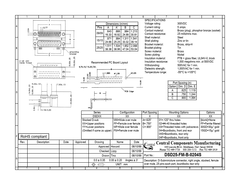
Date Approved Drawing Name Approved Howard Checked Lizzy Drawn Tina 0.0 ± 0.35
1 2 3 4
Port Spacing Mounting Options X XX A=.625” 01=.120” thru holes B=.750” 02=#4-40 threaded holes C=.900” 03=Threaded holes with jackscrews 04=Boardlocks, front and rear 04S=Boardlocks, rear only 04F=Boardlocks, fro
Full PDF Text Transcription for DSD25-FM-B-0204S (Reference)
Note: Below is a high-fidelity text extraction (approx. 800 characters) for
DSD25-FM-B-0204S. For precise diagrams, and layout, please refer to the original PDF.
1 2 3 4 5 6 7 8 9 A B Dimensions (in/mm) A A’ B .643 .666 .984 09/09 16.33 16.92 24.99 .971 .994 1.311 15/15 24.66 25.25 33.32 1.511 1.534 1.852 25/25 38.38 38.96 47.04 P...
View more extracted text
11 15/15 24.66 25.25 33.32 1.511 1.534 1.852 25/25 38.38 38.96 47.04 Pins C 1.213 30.81 1.541 39.14 2.088 53.04 Recommended PC Board Layout C SPECIFICATIONS Voltage rating: Current rating: Contact material: Contact resistance: Shell material: Shell plating: Bracket material: Bracket plating: Screw material: Screw plating: Insulation material: Insulation resistance: Withstanding: Dielectric strength: Temperature range: 300VDC 5 amps Brass (plug), phosphor bronze (socket) 25 milliohms max. Steel Zinc or tin Brass, strip-H Tin Brass Nickel PTB + glass fiber, UL94V-0, black 1,000 megohms min. at 500VDC 500VAC for 1 min. 1,000V