Leaded Schottky Barrier Rectifiers
SB320-G Thru. SB3100-G
Voltage: 20 to 100 V
Current: 3.0 A
RoHS Device
Features
-Low drop down voltage.
-Metal-Semiconductor junction with guard ring
-High surge current capability
-Silicon epitaxial planar chips.
-For use in low voltage, high efficiency inverters,
free wheeling, and polarity protection applications
-Lead-free part, meet RoHS requirements.
Comchip
SMD Diode Specialist
DO-201AD
0.210(5.3)
0.189(4.8)
1.0(25.4) Min.
0.375(9.5)
0.287(7.3)
Mechanical data
-Epoxy: UL94-V0 rated flame retardant
-Case: Molded plastic body DO-201AD
-Terminals: Solderable per MIL-STD-750 Method 2026
-Polarity: Color band denotes cathode end
-Mounting Position: Any
-Weight: 1.12grams
0.052(1.30)
0.048(1.20)
1.0(25.4) Min.
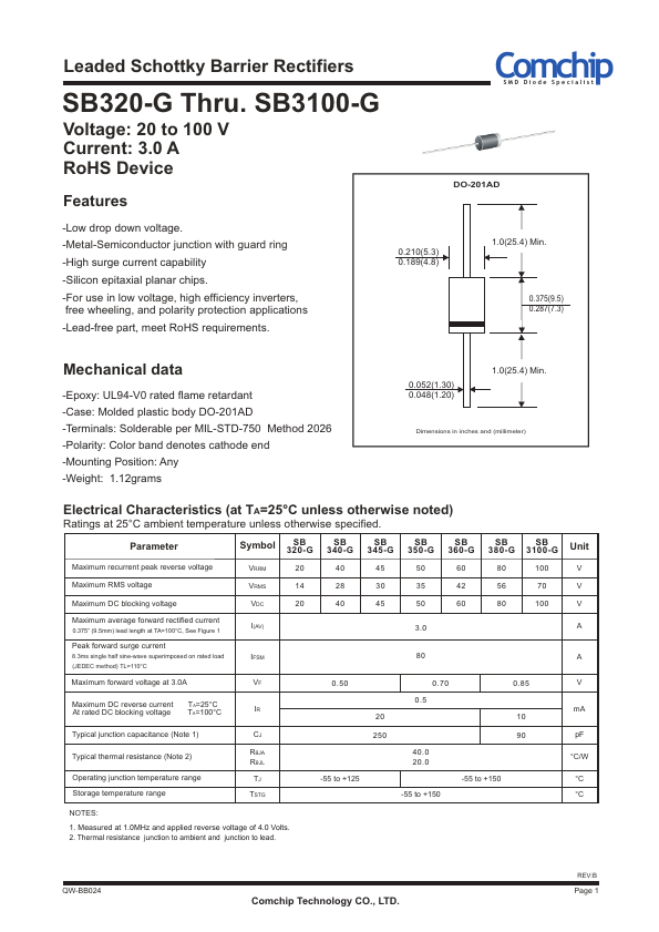
Dimensions in inches and (millimeter)
Electrical Characteristics (at TA=25°C unless otherwise noted)
Ratings at 25°C ambient temperature unless otherwise specified.
Parameter
Maximum recurrent peak reverse voltage
Symbol
SB
320-G
VRRM
20
SB
340-G
40
SB
345-G
45
SB
350-G
50
SB
360-G
60
SB
380-G
SB
3100-G
Unit
80 100 V
Maximum RMS voltage
VRMS
14
28
30
35
42
56
70
V
Maximum DC blocking voltage
Maximum average forward rectified current
0.375” (9.5mm) lead length at TA=100°C, See Figure 1
Peak forward surge current
8.3ms single half sine-wave superimposed on rated load
(JEDEC method) TL=110°C
Maximum forward voltage at 3.0A
Maximum DC reverse current TA=25°C
At rated DC blocking voltage TA=100°C
VDC
I(AV)
IFSM
VF
IR
20 40 45
0.50
20
50 60
3.0
80
0.70
0.5
80 100 V
A
0.85
10
A
V
mA
Typical junction capacitance (Note 1)
Typical thermal resistance (Note 2)
Operating junction temperature range
Storage temperature range
CJ
RθJA
RθJL
TJ
TSTG
250
40.0
20.0
-55 to +125
-55 to +150
90
-55 to +150
pF
°C/W
°C
°C
NOTES:
1. Measured at 1.0MHz and applied reverse voltage of 4.0 Volts.
2. Thermal resistance junction to ambient and junction to lead.
QW-BB024
Comchip Technology CO., LTD.
REV:B
Page 1