74HC595T16 Overview
Key Specifications
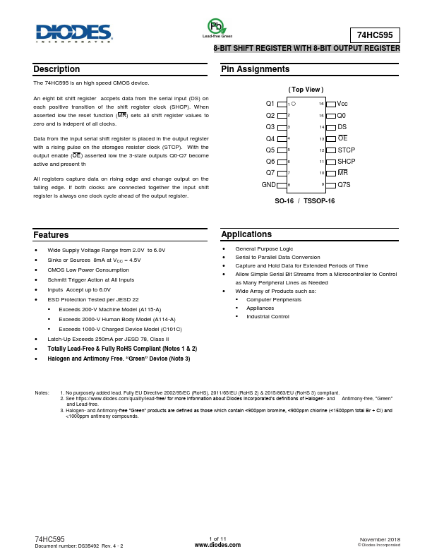
Package: TSSOP
Mount Type: Surface Mount
Pins: 16
Operating Voltage: 4.5 V
Description
The 74HC595 is an high speed CMOS device. An eight bit shift register accpets data from the serial input (DS) on each positive transition of the shift register clock (SHCP).
Key Features
- Wide Supply Voltage Range from 2.0V to 6.0V
- Sinks or Sources 8mA at VCC = 4.5V
- CMOS Low Power Consumption
- Schmitt Trigger Action at All Inputs
- Inputs Accept up to 6.0V