DESCRIPTION
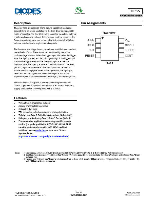
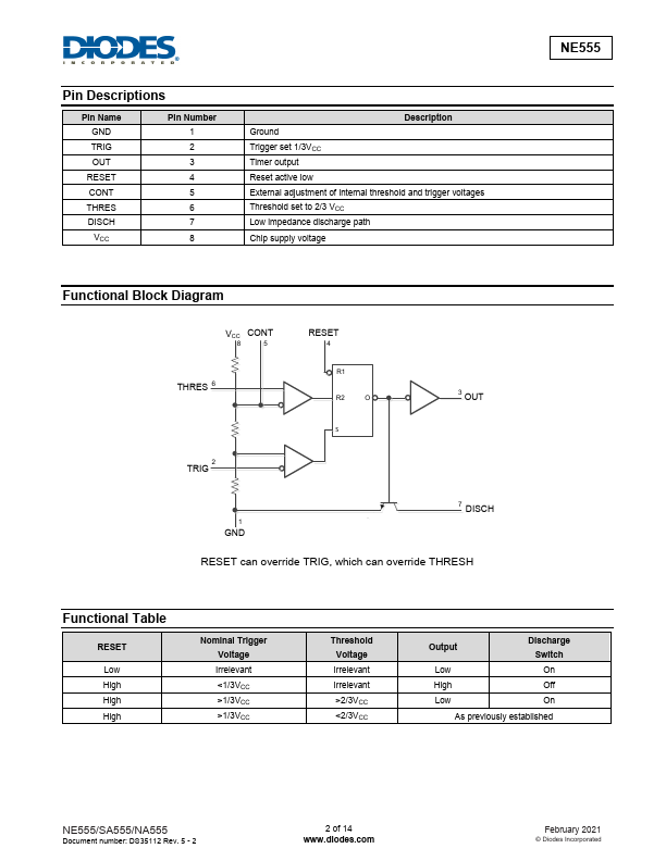
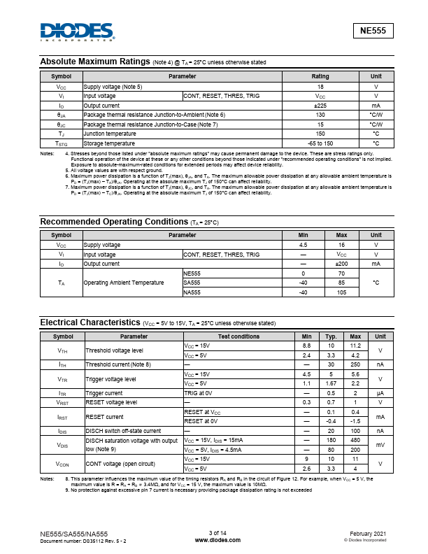
These devices are precision timing circuits capable of producing accurate time delays or oscillation. In the time-delay or monostable mode of operation, the timed interval is controlled by a single external resistor and capacitor network. In the astable mode of operation, the frequency and duty cycle can be controlled independently with two external resistors and a single external capacitor. When the trigger input falls below the trigger level, the flip-flop is set, and the output goes high. If the trigger input is above the trigger level and the threshold input is above the threshold level, the flip-flop is reset and the output is low. The reset (RESET) input can override all other inputs and can be used to initiate a new timing cycle. When RESET goes low, the flip-flop is reset, and the output goes low. When the output is low, a lowimpedance path is provided between discharge (DISCH) and ground. Pin Assignments GND TRIG OUT RESET (Top View) SO-8 The output circuit is capable of sinking or sourcing current up to 200mA. Diodes Incorporated