PAM8620 Description
The PAM8620 is a 15W (per channel) stereo Class-D audio amplifier which offers low THD+N (0.2%), low EMI and good PSRRd thus highquality sound reproduction. The PAM8620 runs off of an 8V to 26V supply at much higher efficiency than petitors’ Ics. The PAM8620 only requires very few external ponents, significantly saving cost and board space.
PAM8620 Key Features
- 15Wx2 Into a 8Ω Speaker
- Low Noise: -90dB
- Over 90% Efficiency
- Shutdown/ Mute Function
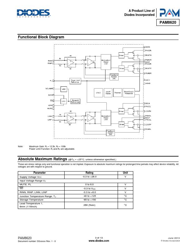
- Over Current ,OVP,UVLO,Thermal and Short-Circuit Protection
- Low THD+N
- Power Limit with Non-Clip
- Low Quiescent Current
- Pop Noise Suppression
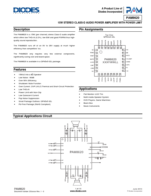
- Small Package Outlines: QFN5x5-32L