Datasheet Summary
ZMY1, ZMY3.0G ... ZMY9.1G, ZMY10 ... ZMY200
ZMY1, ZMY3.0G ... ZMY9.1G, ZMY10 ... ZMY200 SMD Zener Diodes SMD Zener-Dioden
Ptot = 1 W, 1.3W VZ = 1 V ... 200 V Tjmax = 150°C, 175°C
Version 2016-07-04
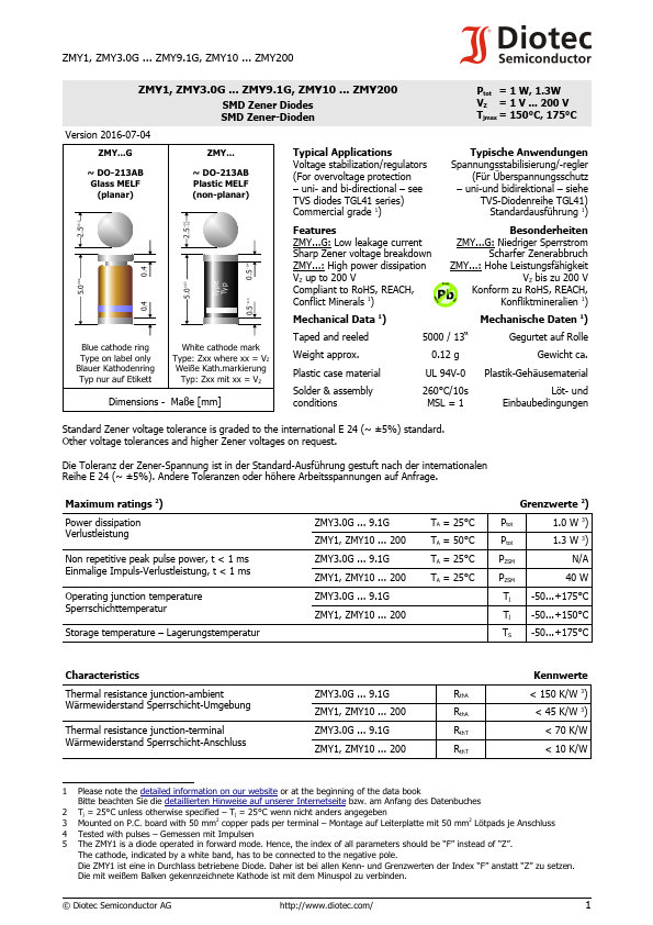
ZMY...G
~ DO-213AB Glass MELF
(planar)
ZMY...
~ DO-213AB Plastic MELF (non-planar)
Typical Applications Voltage stabilization/regulators (For overvoltage protection
- uni- and bi-directional
- see TVS diodes TGL41 series) mercial grade 1)
Typische Anwendungen Spannungsstabilisierung/-regler
(Für Überspannungsschutz
- uni-und bidirektional
- siehe
TVS-Diodenreihe TGL41) Standardausführung 1)
0.1 0.2
_+2.5
2.5±0.2
0.5 _0.4
Features
Besonderheiten
ZMY...G: Low leakage...