
JRM-24064B Description
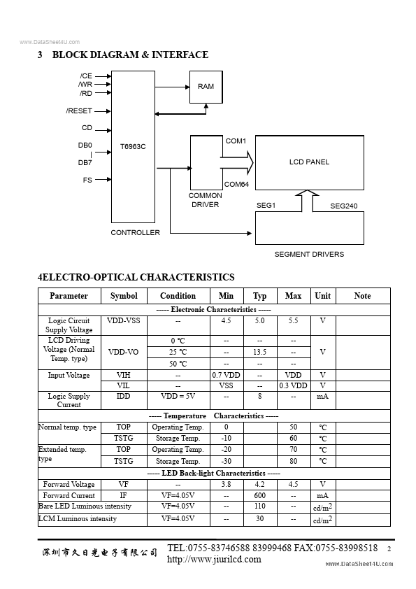
Data Write RD = L --- C/D = H : 3 BLOCK DIAGRAM & INTERFACE /CE /WR /RD /RESET CD DB0 | DB7 FS MON DRIVER T6963C 1 LCD PANEL 64 SEG1 SEG240 RAM CONTROLLER SEGMENT DRIVERS 4ELECTRO-OPTICAL CHARACTERISTICS Parameter Logic Circuit Supply Voltage LCD Driving Voltage (Normal Temp. type) Input Voltage Logic Supply Current Normal temp.