M01N60
FEATURE
Robust High Voltage Temination. Avalanche Energy Specified Source-to Drain Diode Recovery Time parable to a Discrete Fast Recovery Diode Diode is Characterized for Use in Bridge Circurits IDSS and VDS(on) Specified at Elevated Temperature
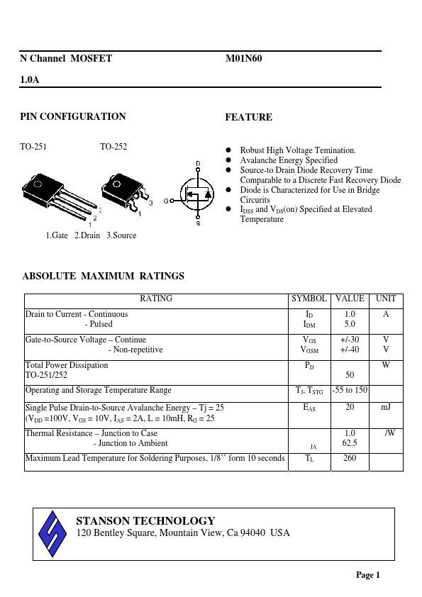
1.Gate 2.Drain 3.Source
ABSOLUTE MAXIMUM RATINGS
RATING Drain to Current
- Continuous
- Pulsed Gate-to-Source Voltage
- Continue
- Non-repetitive Total Power Dissipation TO-251/252 Operating and Storage Temperature Range Single Pulse Drain-to-Source Avalanche Energy
- Tj = 25¢J (VDD =100V, VGS = 10V, IAS = 2A, L = 10m H, RG = 25£[) Thermal Resistance
- Junction to Case
- Junction to Ambient Maximum Lead Temperature for Soldering Purposes, 1/8’’ form 10 seconds SYMBOL VALUE ID IDM VGS VGSM PD 50 TJ, TSTG EAS £ c £c -55 to 150 20 1.0 62.5 260 ¢J m J ¢J /W ¢J 1.0 5.0 +/-30 +/-40 UNIT A V V W
STANSON TECHNOLOGY
120 Bentley Square, Mountain View, Ca 94040 USA TEL: (650) 9389294 FAX: (650) 9389295
Page 1
N Channel MOSFET...