PBL3717-2 Description
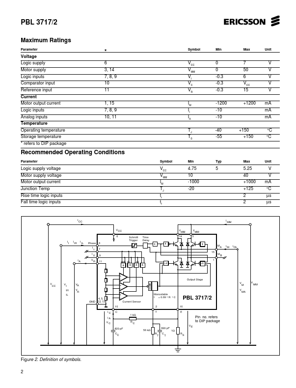
PBL 3717/2 is a bipolar monolithic circuit intended to control and drive the current in one winding of a stepper motor. The circuit consists of a LS-TTL patible logic input stage, a current sensor, a monostable multivibrator and a high power H-bridge output stage with built-in protection diodes. Two PBL 3717/2 and a small number of external ponents form a plete control and drive unit for LS-TTL or...
PBL3717-2 Key Features
- Half-step and full-step modes
- Switched mode bipolar constant current drive
- Wide range of current control 5
- 1200 mA
- Wide voltage range 10
- Designed for unstabilized motor supply voltage
- Current levels can be selected in steps or varied continuously
- Thermal overload protection
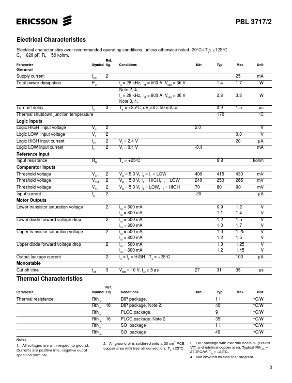
- C off T T Current Sensor
- refers to DIP package