KA558B Overview
Description
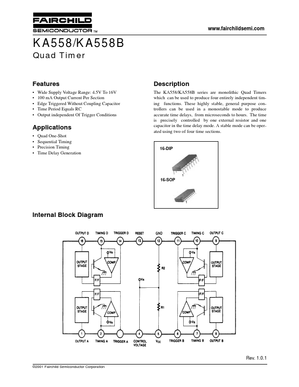
The KA558/KA558B series are monolithic Quad Timers which can be used to produce four entirely independent timing functions. These highly stable, general purpose controllers can be used in a monostable mode to produce accurate time delays, from microseconds to hours.