5.0SMCJ110A Description
SMD Transient Voltage Suppressor 5.0SMCJ Series Formosa MS List List................................................................................................. 1 Package outline...............................................................................
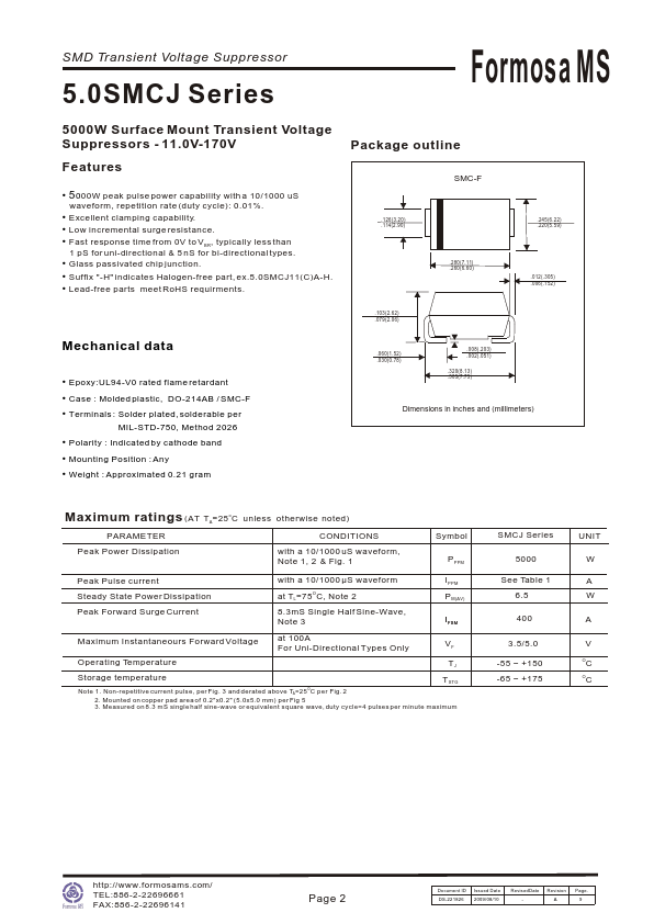
5.0SMCJ110A Key Features
- 2 Mechanical data
- 2 Maximum ratings
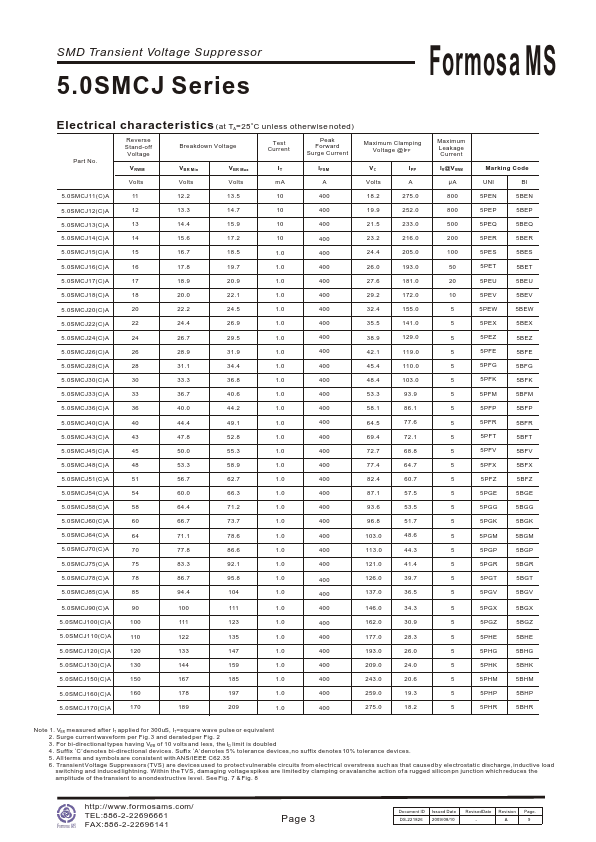
- 2 Electrical characteristics
- 3 Rating and characteristic curves
- 4.5 Pinning information
- 6 Suggested solder pad layout
- 6 Packing information