TK6P60W
TK6P60W is N-Channel MOSFET manufactured by Freescale Semiconductor.
Features
(1) (2) (3) Low drain-source on-resistance: RDS(ON) = 0.68 Ω (typ.) by used to Super Junction Structure : DTMOS Easy to control Gate switching Enhancement mode: Vth = 2.7 to 3.7 V (VDS = 10 V, ID = 0.31 m A)
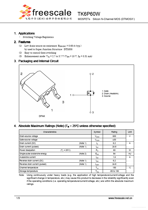
3. Packaging and Internal Circuit
1: Gate 2: Drain (Heatsink) 3: Source
DPAK
4. Absolute Maximum Ratings (Note) (Ta = 25 unless otherwise specified)
Characteristics Drain-source voltage Gate-source voltage Drain current (DC) Drain current (pulsed) Power dissipation Single-pulse avalanche energy Avalanche current Reverse drain current (DC) Reverse drain current (pulsed) Channel temperature Storage temperature (Note 1) (Note 1) (Tc = 25) (Note 2) (Note 1) (Note 1) Symbol VDSS VGSS ID IDP PD EAS IAR IDR IDRP Tch Tstg Rating 600 ±30 6.2 24.8 60 84 1.6 6.2 24.8 150 -55 to 150 W m J A A Unit V
Note:
Using continuously under heavy loads (e.g. the application of high temperature/current/voltage and the significant change in temperature, etc.) may cause this product to decrease in the reliability significantly even if the operating conditions (i.e. operating temperature/current/voltage, etc.) are within the absolute maximum ratings.
1/9
.freescale.net.cn
Free Datasheet http://../
5. Thermal Characteristics
Characteristics Channel-to-case thermal resistance Symbol Rth(ch-c) Max 2.09 Unit /W
Note 1: Ensure that the channel temperature does not exceed 150. Note 2: VDD = 90 V, Tch = 25 (initial), L = 57.6 m H, RG = 25 Ω, IAR = 1.6 A
Note:
This transistor is sensitive to electrostatic discharge and should be handled with care.
2/9
.freescale.net.cn
Free Datasheet http://../
6. Electrical Characteristics 6.1. Static Characteristics (Ta = 25 unless otherwise specified)
Characteristics Gate leakage current Drain cut-off current Drain-source breakdown voltage Gate threshold voltage Drain-source on-resistance Symbol IGSS IDSS V(BR)DSS Vth RDS(ON) Test Condition VGS = ±30 V, VDS = 0 V VDS = 600 V, VGS = 0 V ID = 10 m A, VGS = 0 V VDS = 10 V, ID = 0.31...