5.0SMCJ12 Overview
Key Specifications
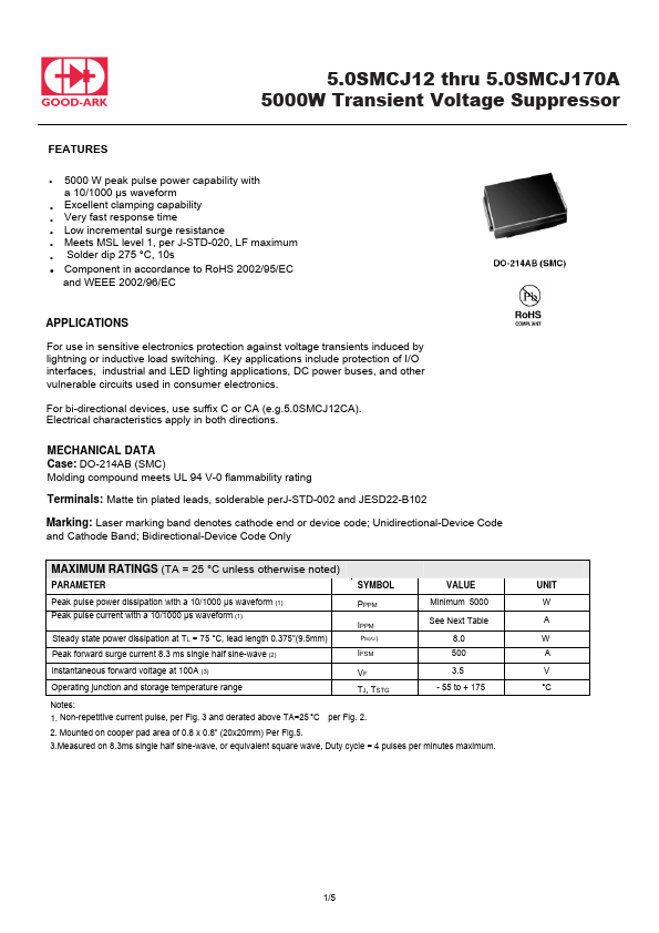
Key Features
- 5000 W peak pulse power capability with a 10/1000 µs waveform
- Excellent clamping capability
- Very fast response time
- Low incremental surge resistance
- Meets MSL level 1, per J-STD-020, LF maximum
| Part | 5.0SMCJ12 |
|---|---|
| Description | 5000W Transient Voltage Suppressor |
| Manufacturer | Good-Ark Semiconductor |
| Size | 1.22 MB |
| Seller | Inventory | Price Breaks | Buy |
|---|---|---|---|
| DigiKey | 0 | 3000+ : 0.24178 USD 6000+ : 0.22288 USD 9000+ : 0.21325 USD 15000+ : 0.20425 USD |
View Offer |
| Avnet | 0 | 3000+ : 0.20899 USD 6000+ : 0.20792 USD 12000+ : 0.20685 USD 24000+ : 0.20579 USD |
View Offer |
| Part Number | Manufacturer | Description |
|---|---|---|
| 5.0SMCJ12 | Won-Top Electronics | 5000W SURFACE MOUNT TRANSIENT VOLTAGE SUPPRESSOR |
| 5.0SMCJ120 | MAYLOON | 5000W Surface Mount Transient Voltage Suppressor |
| 5.0SMCJ12 | MAYLOON | 5000W Surface Mount Transient Voltage Suppressor |
| 5.0SMCJ12 | HITANO | Transient Voltage Suppressors |
| 5.0SMCJ120A | Diotec Semiconductor | SMD Transient Voltage Suppressor Diodes |