• Part: SK22
  • Description: SURFACE MOUNT SCHOTTKY BARRIER RECTIFIER
  • Manufacturer: Good-Ark Semiconductor
  • Size: 182.20 KB
Download SK22 Datasheet PDF
Good-Ark Semiconductor
SK22
SK22 is SURFACE MOUNT SCHOTTKY BARRIER RECTIFIER manufactured by Good-Ark Semiconductor.
- Part of the SK22_GOOD comparator family.
Features Plastic package has underwriters Laboratory Flammability Classification 94V-0 For surface mounted applications Low profile package Built-in strain relief Metal to silicon rectifier, majority carrier conduction Low power loss, high efficiency High current capability, low V F High surge capacity For use in low voltage high frequency inverters, free wheeling, and polarity protection applications High temperature soldering guaranteed: 260 /10 seconds at terminals D 
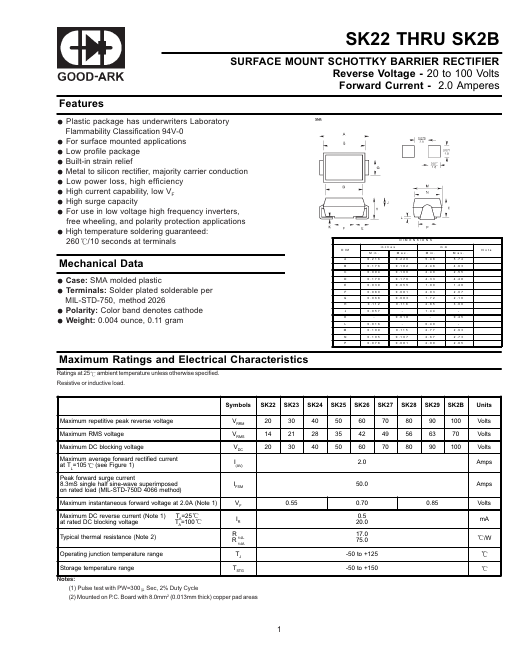
IM M in . 0 .2 1 6 0 .1 7 6 0 .0 9 4 0 .1 7 0 0 .0 3 9 0 .0 8 0 0 .0 6 8 0 .1 1 2 0 .0 5 7 0 .0 1 6 0 .1 0 9 0 .1 0 5 0 .0 7 8 D IM E N S IO N S in c h e s M a x . 0 .2 2 6 0 .1 8 2 0 .1 0 0 0 .1 7 6 0 .0 5 5 0 .0 8 1 0 .0 8 3 0 .1 1 8 0 .0 1 8 0 .1 1 5 0 .1 0 7 0 .0 8 1 M in . 5 .4 8 4 .4 8 2 .4 0 4 .3 3 1 .0 0 2 .0 3 1 .7 2 2 .8 5 1 .4 4 0 .4 0 2 .7 7 2 .6 7 2 .0 0 m m M a x . 5 .7 4 4 .6 3 2 .5 5 4 .4 8 1 .4 0 2 .0 7 2 .1 0 3 .0 0 0 .4 5 2 .9 3 2 .7 3 2 .0 5 N o te Mechanical Data Case: SMA molded plastic Terminals: Solder plated solderable per MIL-STD-750, method 2026 Polarity: Color band denotes cathode Weight: 0.004 ounce, 0.11 gram A B C D E F G H J K L M N P Maximum Ratings and Electrical Characteristics Ratings at 25 ambient temperature unless otherwise specified. Resistive or inductive load. Symbols SK23 SK24 SK25 SK26 SK27 SK28 SK29 SK2B Units Maximum repetitive peak reverse voltage Maximum RMS voltage Maximum DC blocking voltage Maximum average forward rectified current at TL=105 (see Figure 1) Peak forward surge current 8.3m S single half sine-wave superimposed on rated load (MIL-STD-750D 4066 method) Maximum instantaneous forward voltage at 2.0A (Note 1) Maximum DC reverse current (Note 1) at rated DC blocking voltage Typical thermal resistance (Note 2) Operating junction temperature range Storage temperature range TA=25 TA=100 VRRM VRMS VDC I(AV) IFSM VF IR R R JL JA 20 14 20 30 21 30 40 28 40 50 35 50 60 42 60 2.0 50.0 70 49 70 80 56 80 90 63 90 100 70...