Datasheet Summary
Cascadable Silicon Bipolar MMIC␣ Amplifier Technical Data
Features
- Cascadable 50 Ω Gain Block
- 3 dB Bandwidth: DC to 2.8 GHz
- 12.0 dB Typical Gain at 1.0␣ GHz
- Unconditionally Stable (k>1)
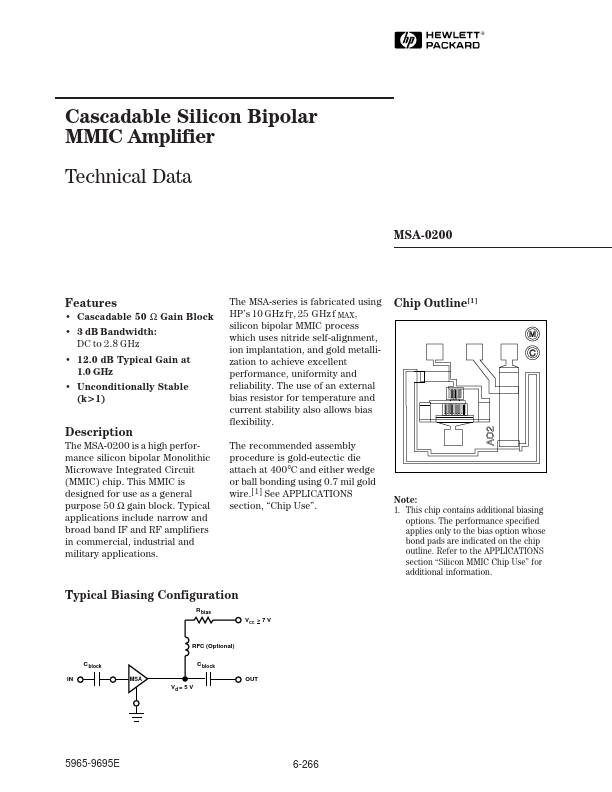
The MSA-series is fabricated using HP’s 10 GHz fT, 25␣ GHz f MAX, silicon bipolar MMIC process which uses nitride self-alignment, ion implantation, and gold metallization to achieve excellent performance, uniformity and reliability. The use of an external bias resistor for temperature and current stability also allows bias flexibility. The remended assembly procedure is gold-eutectic die attach at 400°C and either wedge or ball bonding using 0.7 mil gold wire.[1] See APPLICATIONS...