Datasheet4U.com
🌙
2SC4807 Datasheet | Hitachi Semiconductor
Part:
2SC4807
Description:
NPN TRANSISTOR
Category:
Transistor
Manufacturer:
Hitachi Semiconductor
Size:
46.81 KB
2SC4807 Datasheet (PDF) Download
Hitachi Semiconductor
2SC4807
Key Features
High gain bandwidth product fT = 4.4 GHz Typ
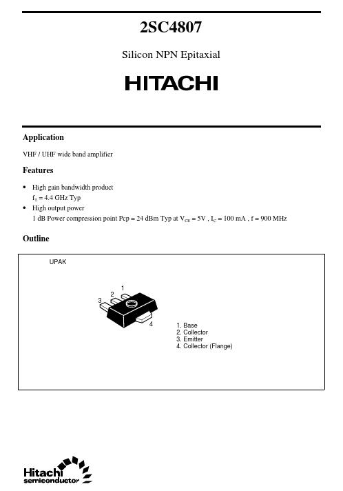
High output power 1 dB Power pression point Pcp = 24 dBm Typ at VCE = 5V , I C = 100 mA , f = 900 MHz Outline UPAK 1 3 2 4
Collector (Flange) 2SC4807
×
Close