2SK359
Overview
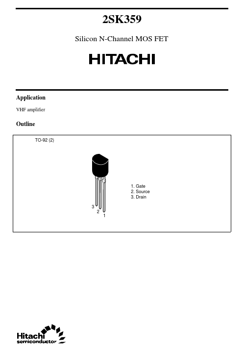
2SK359 Silicon N-Channel MOS FET Application VHF amplifier Outline TO-92 (2) 1. Gate 2. Source 3. Drain 3 2 1 2SK359 Absolute Maximum Ratings (Ta = 25°C) Item Drain to source voltage Gate to sourc...
| Part | 2SK359 |
|---|---|
| Description | N-Channel MOSFET |
| Category | MOSFET |
| Manufacturer | Hitachi Semiconductor |
| Size | 31.62 KB |
2SK359 Silicon N-Channel MOS FET Application VHF amplifier Outline TO-92 (2) 1. Gate 2. Source 3. Drain 3 2 1 2SK359 Absolute Maximum Ratings (Ta = 25°C) Item Drain to source voltage Gate to sourc...
| Part Number | Manufacturer | Description |
|---|---|---|
| K3594-01 | Fuji Electric | 2SK3594-01 |
| K3595-01MR | Fuji Electric | 2SK3595-01MR |
| 2SK3592-01SJ | Fuji Electric | N-CHANNEL SILICON POWER MOSFET |
| K3591 | Fuji Electric | 2SK3591-01MR |
| K3596-01L | Fuji Electric | 2SK3596-01L |