G1000LL250
Description
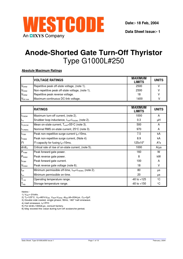
Date:- 18 Feb, 2004 Data Sheet Issue:- 1 Anode-Shorted Gate Turn-Off Thyristor Type G1000L#250 Absolute Maximum Ratings VDRM VRSM VRRM VDC-link VOLTAGE RATINGS Repetitive peak off-state voltage, (...
Date:- 18 Feb, 2004 Data Sheet Issue:- 1 Anode-Shorted Gate Turn-Off Thyristor Type G1000L#250 Absolute Maximum Ratings VDRM VRSM VRRM VDC-link VOLTAGE RATINGS Repetitive peak off-state voltage, (...