IXGQ85N33PCD1 Overview
Key Specifications
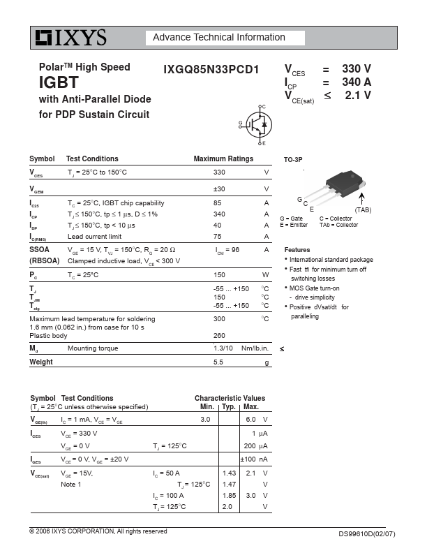
Mount Type: Through Hole
Pins: 3
Max Operating Temp: 150 °C
Min Operating Temp: -55 °C
Key Features
- International standard package
- Fast tfi for minimum turn off switching losses
- MOS Gate turn-on
- drive simplicity