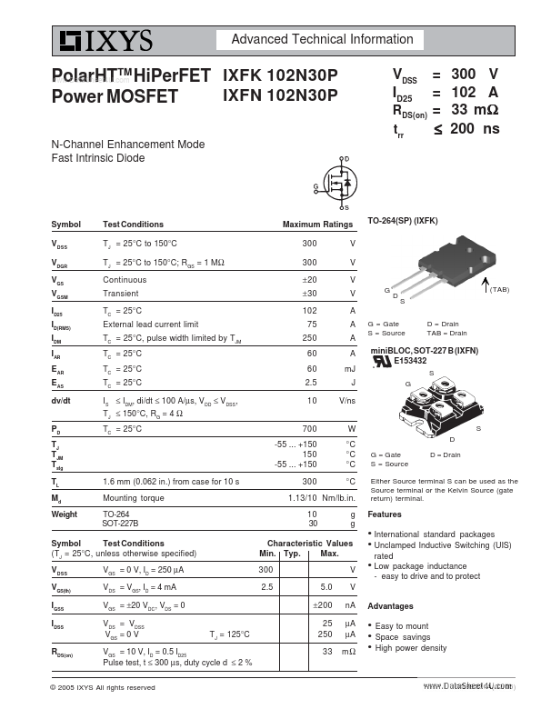
Datasheet4U Logo Datasheet4U.com

IXFN102N30P - Polar MOSFETs

Download the IXFN102N30P datasheet PDF. This datasheet also covers the IXFK102N30P variant, as both devices belong to the same polar mosfets family and are provided as variant models within a single manufacturer datasheet.

Features

  • z Symbol Test Conditions (TJ = 25°C, unless otherwise specified) VDSS VGS(th) IGSS IDSS RDS(on) VGS = 0 V, ID = 250 µA VDS = VGS, ID = 4 mA VGS = ±20 VDC, VDS = 0 VDS = VDSS VGS = 0 V TJ = 125°C Characteristic Values Min. Typ. Max. 300 2.5 5.0 ±200 25 250 33 V V nA µA µA mΩ z z International standard packages Unclamped Inductive Switching (UIS) rated Low package inductance - easy to drive and to protect Advantages z z z VGS = 10 V, ID = 0.5 ID25 Pulse test, t ≤ 300 µs, duty cycle d ≤ 2 %.

📥 Download Datasheet

Note: The manufacturer provides a single datasheet file (IXFK102N30P_IXYSCorporation.pdf) that lists specifications for multiple related part numbers.

Full PDF Text Transcription

Click to expand full text
Advanced Technical Information www.DataSheet4U.com PolarHTTM HiPerFET IXFK 102N30P IXFN 102N30P Power MOSFET N-Channel Enhancement Mode Fast Intrinsic Diode VDSS ID25 RDS(on) trr = = = ≤ 300 V 102 A 33 mΩ 200 ns Symbol VDSS VDGR VGS VGSM ID25 ID(RMS) IDM IAR EAR EAS dv/dt PD TJ TJM Tstg TL Md Weight Test Conditions TJ = 25°C to 150°C TJ = 25°C to 150°C; RGS = 1 MΩ Continuous Transient TC = 25°C External lead current limit TC = 25°C, pulse width limited by TJM TC = 25°C TC = 25°C TC = 25°C IS ≤ IDM, di/dt ≤ 100 A/µs, VDD ≤ VDSS, TJ ≤ 150°C, RG = 4 Ω TC = 25°C Maximum Ratings 300 300 ± 20 ± 30 102 75 250 60 60 2.5 10 700 -55 ... +150 150 -55 ...
Published: |