C = Collector
A A A W °C °C °C °C V~ N/lb. g
z z z z
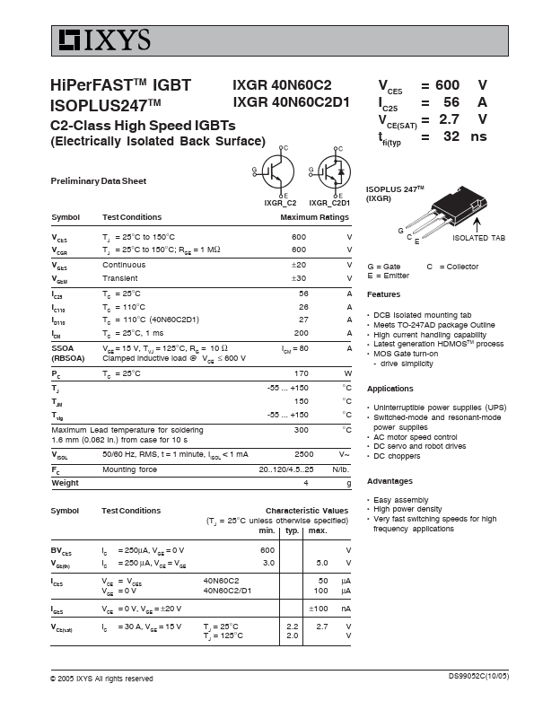
DCB Isolated mounting tab Meets TO-247AD package Outline High current handling capability Latest generation.
Full PDF Text Transcription for IXGR40N60C2 (Reference)
Note: Below is a high-fidelity text extraction (approx. 800 characters) for
IXGR40N60C2. For precise diagrams, tables, and layout, please refer to the original PDF.
HiPerFASTTM IGBT ISOPLUS247TM IXGR 40N60C2 IXGR 40N60C2D1 VCES IC25 C2-Class High Speed IGBTs (Electrically Isolated Back Surface) Preliminary Data Sheet IXGR_C2 IXGR_C2D...
View more extracted text
rically Isolated Back Surface) Preliminary Data Sheet IXGR_C2 IXGR_C2D1 = = VCE(SAT) = tfi(typ = 600 V 56 A 2.7 V 32 ns ISOPLUS 247TM (IXGR) Symbol VCES VCGR VGES VGEM IC25 IC110 ID110 ICM SSOA (RBSOA) PC TJ TJM Tstg Test Conditions TJ = 25°C to 150°C TJ = 25°C to 150°C; RGE = 1 MΩ Continuous Transient TC = 25°C TC = 110°C TC = 110°C (40N60C2D1) TC = 25°C, 1 ms VGE = 15 V, TVJ = 125°C, RG = 10 Ω Clamped inductive load @ VCE ≤ 600 V TC = 25°C Maximum Ratings 600 600 ± 20 ± 30 56 26 27 200 ICM = 80 170 -55 ... +150 150 -55 ... +150 300 2500 20..120/4.5..25 4 V V V V A A z G C E ISOLATED TAB G = Gate E = Emitter Features C =