IXGT24N170 Description
+150 300 260 1.13/10 6 4 W °C °C °C °C °C Nm/lb.in. g g Characteristic Values Min.
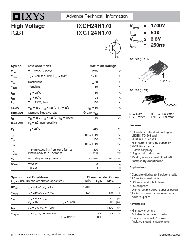
IXGT24N170 Key Features
- drive simplicity z Rugged NPT structure z Molding epoxies meet UL 94 V-0
IXGT24N170 is High Voltage IGBT manufactured by IXYS.

| Manufacturer | Part Number | Description |
|---|---|---|
| IXGT24N170A | High Voltage IGBT | |
| IXGT24N170AH1 | High Voltage IGBT |
+150 300 260 1.13/10 6 4 W °C °C °C °C °C Nm/lb.in. g g Characteristic Values Min.