Silicon chip on Direct-Copper Bond (DCB) substrate Isolated mounting surface 2500V electrical isolation
Advantages
Easy to mount Space savings High power density.
Full PDF Text Transcription for IXTC200N10T (Reference)
Note: Below is a high-fidelity text extraction (approx. 800 characters) for
IXTC200N10T. For precise diagrams, and layout, please refer to the original PDF.
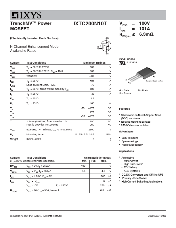
TrenchMVTM Power MOSFET (Electrically Isolated Back Surface) N-Channel Enhancement Mode Avalanche Rated IXTC200N10T Symbol VDSS VDGR VGSM ID25 ILRMS IDM IA EAS PD TJ TJM ...
View more extracted text
ted IXTC200N10T Symbol VDSS VDGR VGSM ID25 ILRMS IDM IA EAS PD TJ TJM Tstg TL VISOL Md Weight Test Conditions TJ = 25°C to 175°C TJ = 25°C to 175°C, RGS = 1MΩ Transient Maximum Ratings 100 100 ± 30 V V V TC = 25°C Lead Current Limit, RMS TC = 25°C, pulse width limited by TJM TC = 25°C TC = 25°C TC = 25°C 101 75 500 40 1.5 160 -55 ... +175 175 -55 ... +175 A A A A J W °C °C °C 1.6mm (0.062in.) from case for 10s Plastic body for 10 seconds 300 °C 260 °C 50/60Hz, t = 1 minute, IISOL < 1mA, RMS 2500 Mounting force 11..65 / 2.5..14.6 V N/lb.