F8152
F8152 is SAW Bandpass Filter manufactured by Integrated Technology Future.
Features z z z z z RF bandpass filter High attenuation Usable bandwidth 19MHz No matching 50Ω single-ended operation Ceramic Surface Mounted Device (SMD) Package
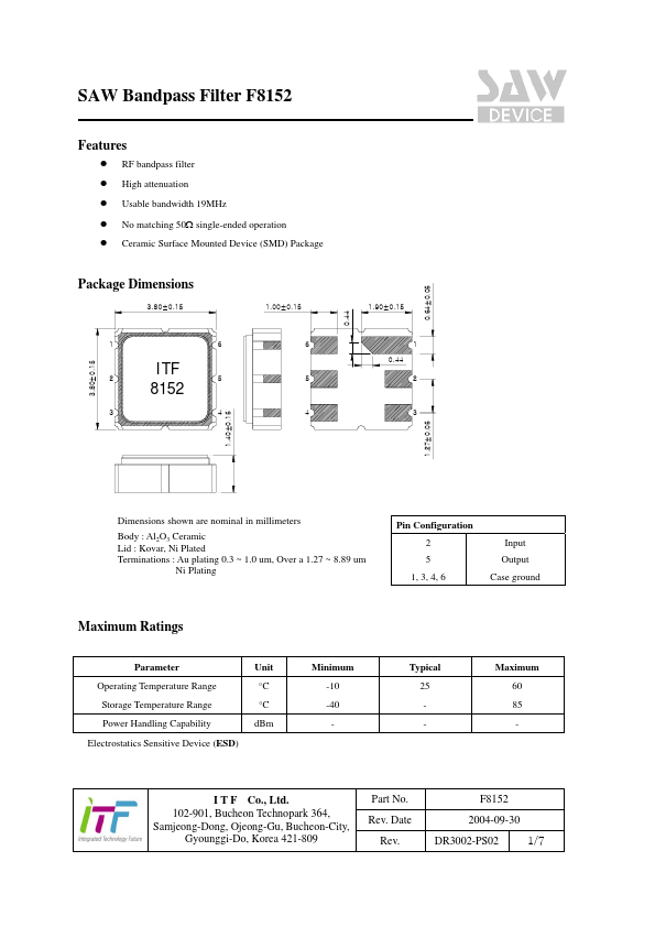
3.80±0.15
1.00±0.15 0.44
1.90±0.15
6 0.44
ITF 8152
3.80±0.15
1.40±0.15
3 1.27±0.05
Dimensions shown are nominal in millimeters Body : Al2O3 Ceramic Lid : Kovar, Ni Plated Terminations : Au plating 0.3 ~ 1.0 um, Over a 1.27 ~ 8.89 um Ni Plating
Pin Configuration 2 5 1, 3, 4, 6 Input Output Case ground
Maximum Ratings
Parameter Operating Temperature Range Storage Temperature Range Power Handling Capability Electrostatics Sensitive Device (ESD) Unit °C °C d Bm Minimum -10 -40 Typical 25 Maximum 60 85
- I T F Co., Ltd. 102-901, Bucheon Technopark 364, Samjeong-Dong, Ojeong-Gu, Bucheon-City, Gyounggi-Do, Korea 421-809
Part No. Rev. Date Rev.
0.64±0.05
Package Dimensions
F8152 2004-09-30 DR3002-PS02 1/7
..net
SAW Bandpass Filter F8152
Specifications
Fc = 815.5MHz Terminating source impedance Terminating load impedance : 50Ω : 50Ω
Minimum Center Frequency ( Fc ) Insertion Loss (Fc +/- 9.5 MHz) Amplitude Ripple (Fc +/- 9.5 MHz) Absolute Group Delay at Fc Group Delay Variation (Fc +/- 9.5 MHz) VSWR (Fc +/- 9.5 MHz) Relative Attenuation … ~ Fc
- 35 MHz Fc + 70 MHz ~ … Temperature Coefficient of Frequency MHz d B d B nsec nsec
- Typical 815.5 3.5 1.0 35 15 1.5
Maximum 4.0 2.0 2.0 d B
45 45
- 50 50 -80
- ppm/°C
- Notes : 1) All specifications are based on the matching schematic shown below, measured by Agilent Network analyzer and full 2 port calibration. 2) Electrical margin has been built into the design to account for the variations due to temperature drift and manufacturing tolerances 3) All attenuation measurements are measured relative to insertion...