120NQ040
120NQ040 is SCHOTTKY RECTIFIER manufactured by International Rectifier.
- Part of the 120NQ035 comparator family.
- Part of the 120NQ035 comparator family.
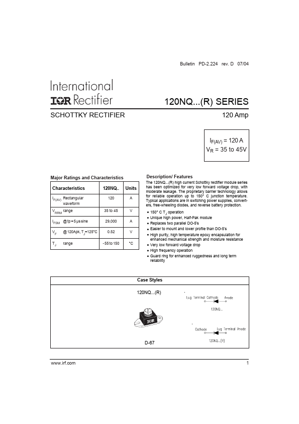
Description
/ Features
The 120NQ...(R) high current Schottky rectifier module series has been optimized for very low forward voltage drop, with moderate leakage. The proprietary barrier technology allows for reliable operation up to 150° C junction temperature. Typical applications are in switching power supplies, converters, free-wheeling diodes, and reverse battery protection.
150° C TJ operation Unique high power, Half-Pak module
Replaces two parallel DO-5's
Easier to mount and lower profile than DO-5's
High purity, high temperature epoxy encapsulation for enhanced mechanical strength and moisture resistance
Very low forward voltage drop
High frequency...