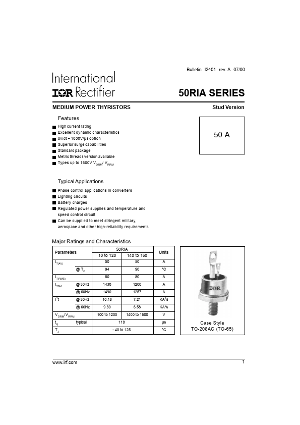
50RIA Series
Bulletin I2401 rev. A 07/00
ELECTRICAL SPECIFICATIONS
Voltage Ratings
Voltage
Type number Code
10
VDRM/VRRM, max. repetitive
peak and off-state voltage (1)
V
100
50RIA
20
40
60
80
100
120
140
160
200
400
600
800
1000
1200
1400
1600
VRSM , maximum non-
repetitive peak voltage (2)
V
150
300
500
700
900
1100
1300
1500
1700
IDRM/IRRM max.
@ TJ =mTAJ max.
15
(1) Units may be broken over non-repetitively in the off-state direction without damage, if dI/dt does not exceed 20A/µs
(2) For voltage pulses with tp ≤ 5ms
On-state Conduction
Parameter
IT(AV)
IT(RMS)
ITSM
Max. average on-state current
@ Case temperature
Max. RMS on-state current
Max. peak, one-cycle
non-repetitive surge current
I2t Maximum I2t for fusing
I2√t Maximum I2√t for fusing
VT(TO)1 Low level value of threshold
voltage
VT(TO)2 High level value of threshold
voltage
rt1 Low level value of on-state
slope resistance
rt2 High level value of on-state
slope resistance
VTM Max. on-state voltage
IH Maximum holding current
IL Latching current
50RIA
10 to 120 140 to 160
50 50
94 90
80 80
1430
1200
1490
1257
1200
1010
1255
1057
10.18
7.21
9.30 6.58
7.20 5.10
6.56 4.65
101.8
72.1
0.94 1.02
1.08 1.17
4.08 4.78
3.34 3.97
1.60
200
1.78
400
Units Conditions
A
°C
A
A
KA2s
KA2√s
V
180° sinusoidal conduction
t = 10ms No voltage
t = 8.3ms reapplied
t = 10ms
t = 8.3ms
100% VRRM
reapplied
Sinusoidal half wave,
t = 10ms
t = 8.3ms
No voltage
reapplied
Initial TJ = TJ max.
t = 10ms
t = 8.3ms
100% VRRM
reapplied
t = 0.1 to 10ms, no voltage reapplied, TJ = TJ max.
(16.7% x π x IT(AV) < I < π x IT(AV)), TJ = TJ max.
(π x IT(AV) < I < 20 x π x IT(AV)), TJ = TJ max.
mΩ (16.7% x π x IT(AV) < I < π x IT(AV)), TJ = TJ max.
(π x IT(AV) < I < 20 x π x IT(AV)), TJ = TJ max.
V Ipk= 157 A, TJ = 25°C
mA TJ = 25°C. Anode supply 22V, resistive load,
Initial IT = 2A
Anode supply 6V, resistive load
2 www.irf.com