50SQ100 Overview
Key Specifications
Mount Type: Through Hole
Pins: 2
Max Operating Temp: 175 °C
Min Operating Temp: -55 °C
Key Features
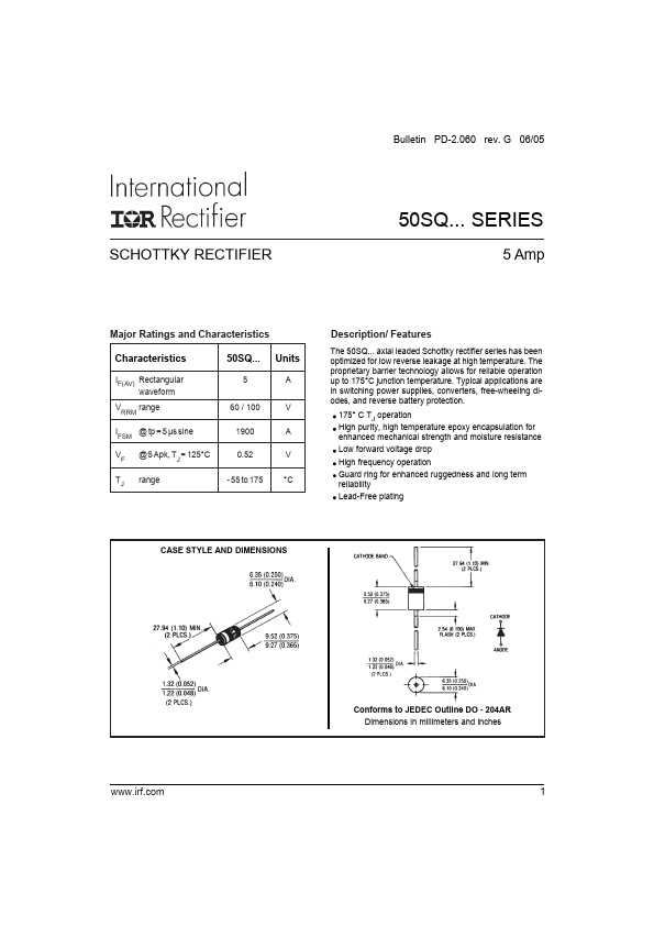
- Units A V A V °C The 50SQ
- axial leaded Schottky rectifier series has been optimized for low reverse leakage at high temperature
- The proprietary barrier technology allows for reliable operation up to 175°C junction temperature
- Typical applications are in switching power supplies, converters, free-wheeling diodes, and reverse battery protection
- 5 60 to 100 1900 0.52 - 55 to 175 CASE STYLE AND DIMENSIONS Conforms to JEDEC Outline DO - 204AR Dimensions in millimeters and inches 1 50SQ