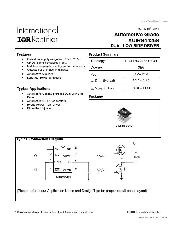
AUIRS4426S Key Features
- Gate drive supply range from 6 V to 20 V CMOS Schmitt-triggered inputs Matched propagation delay for both channels Outpu
- 20 V 2.3 A & 3.3 A 70 ns & 65 ns
AUIRS4426S is DUAL LOW SIDE DRIVER manufactured by International Rectifier.
| Part Number | Description |
|---|---|
| AUIRS4427S | Automotive Grade Dual Low Side Driver |
| AUIRS2003S | Automotive Grade Half Bridge Driver |
| AUIRS2012S | High and low side gate driver |
| AUIRS20162S | High and low side gate driver |
| AUIRS2016S | High Side Driver |
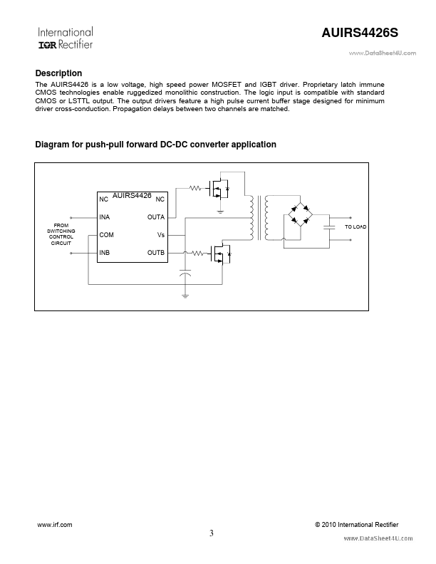
© 2010 International Rectifier 2 AUIRS4426S .. Description The AUIRS4426 is a low voltage, high speed power MOSFET and IGBT driver. Proprietary latch immune CMOS technologies enable ruggedized monolithic construction.