Datasheet Summary
- 95015A
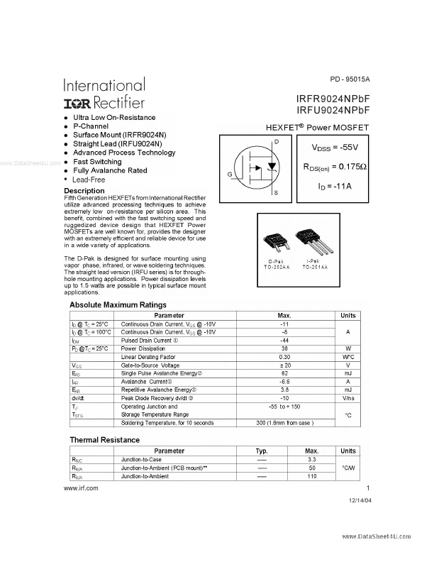
IRFR9024NPbF IRFU9024NPbF
..
- Lead-Free
.irf.
12/14/04
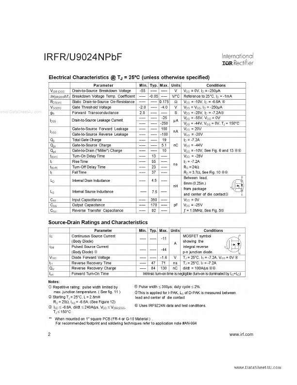
IRFR/U9024NPbF
..
.irf.
IRFR/U9024NPbF
..
.irf.
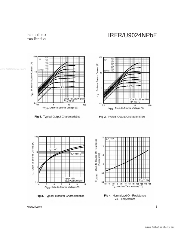
IRFR/U9024NPbF
..
.irf.
IRFR/U9024NPbF
..
.irf.
IRFR/U9024NPbF
..
.irf.
IRFR/U9024NPbF
Peak Diode Recovery dv/dt Test Circuit
+
Circuit Layout Considerations
- Low Stray Inductance
- Ground Plane
- Low Leakage Inductance Current...