IR2233SPBF
IR2233SPBF is 3-PHASE BRIDGE DRIVER manufactured by International Rectifier.
- Part of the IR2235S comparator family.
Features
- Floating channel designed for bootstrap operation Fully operational to +600V or+1200V Tolerant to negative transient voltage d V/dt immune
- Gate drive supply range from 10V/12V to 20V DC and up to 25V for transient
- Undervoltage lockout for all channels
- Over-current shut down turns off all six drivers
- Independent 3 half-bridge drivers
- Matched propagation delay for all channels
- 2.5V logic patible
- Outputs out of phase with inputs
- All parts are also available LEAD-FREE
Product Summary
VOFFSET IO+/-
VOUT ton/off (typ.) Deadtime (typ.)
600V or 1200V max. 200 m A / 420 m A 10
- 20V or 12
- 20V
750/700 ns 250 ns
Packages
Description
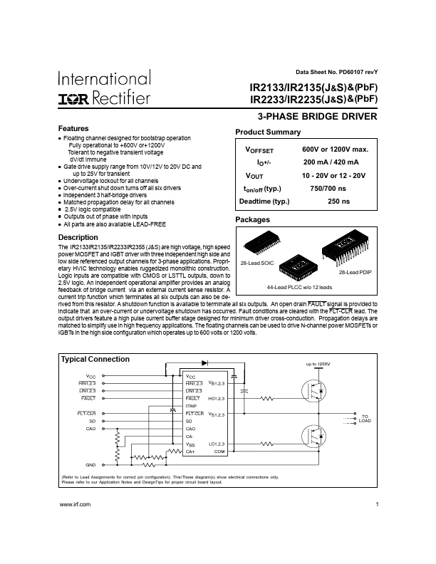
The IR2133IR2135/IR2233IR2355 (J&S) are high voltage, high speed power MOSFET and IGBT driver with three independent high side and low side referenced output channels for 3-phase applications. Proprietary HVIC technology enables ruggedized monolithic construction. Logic inputs are patible with CMOS or LSTTL outputs, down to
28-Lead SOIC
28-Lead PDIP
2.5V logic. An independent operational amplifier provides an analog feedback of bridge current via an external current sense resistor. A
44-Lead PLCC w/o 12 leads current trip function which terminates all six outputs can also be de- rived from this resistor. A shutdown function is available to terminate all six outputs. An open drain FAULT signal is provided to indicate that an over-current or undervoltage shutdown has occurred. Fault conditions are cleared with the FLT-CLR lead. The output drivers feature a high pulse current buffer stage designed for minimum driver cross-conduction. Propagation delays are matched to simplify use in high frequency applications. The floating channels can be used to drive N-channel power MOSFETs or
IGBTs in the high side configuration which operates up to 600 volts or 1200 volts.
Typical Connection up to 600V or 1200V
(Refer to Lead Assignments for correct pin configuration). This/These diagram(s) show electrical...