
International Rectifier Electronic Components Datasheet |
IR2237 Datasheet
(IR2137 / IR2237) 3-PHASE BRIDGE DRIVER
www.DataSheet4U.com
Data Sheet No. PD60170-G
IR2137/IR2237(J)(Q)
Features
3-PHASE BRIDGE DRIVER
• Floating channel up to +600V or +1200V
• “soft” over-current shutdown turns off all six
Product Summary
outputs
• Integrated high side desaturation circuit
• Controlled “soft” turn on for EMI reduction
• Integrated brake IGBT driver
• Three independent low side COM pins
• Separate pull-up/pull-down output drive pins
• Matched delay outputs
• 3.3V logic compatible
• Under voltage lockout with hysteresis band
VOFFSET
IO+/-
VOUT
Brake Io+/-
Matched delay
Deadtime (typ.)
600V max. or 1200V max.
220mA / 460mA
12.5V - 20V
40mA/80mA
75nsec
300 nsec
Description
DESAT Blanking time (typ.)
2.0usec
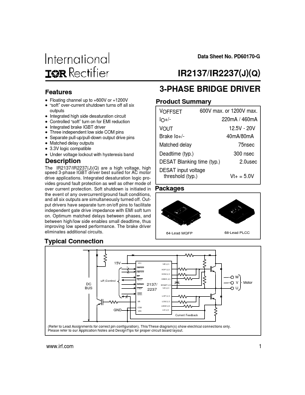
The IR2137/IR2237(J)(Q) are a high voltage, high
speed 3-phase IGBT driver best suited for AC motor
drive applications. Integrated desaturation logic pro-
DESAT input voltage
threshold (typ.)
Vt+ = 5.0V
vides ground fault protection as well as other mode of
over current protection. Soft shutdown is initiated in Packages
the event of any overcurrent/ground fault conditions,
and all six outputs are simultaneously turned off. Out-
put drivers have separate turn on/off pins to facilitate
independent gate drive impedance with EMI soft turn
on. Optimum matched delays between phases, and
between high/low side enables small deadtime, thus
improving low speed performance. The brake driver
eliminates additional circuits.
64-Lead MQFP
68-Lead PLCC
Typical Connection
DC
BUS
15V
3
3
uP,Control
3
GND
VCC
LIN1,2,3
HIN1,2,3
SD
FAULT
FLTCLR
ITRIP
2137/
2237
VB1,2,3
HOP1,2,3
HON1,2,3
HSSD1,2,3
DESAT1,2,3
VS1,2,3
BRIN
LOP1,2,3
BR
COM
VSS
LON1,2,3
LSSD1,2,3
LS1,2,3
Current Feedback
W
V Motor
U
(Refer to Lead Assignments for correct pin configuration). This/These diagram(s) show electrical connections only.
Please refer to our Application Notes and DesignTips for proper circuit board layout.
www.irf.com
1
|
|

International Rectifier Electronic Components Datasheet |
IR2237 Datasheet
(IR2137 / IR2237) 3-PHASE BRIDGE DRIVER
IR2137/IR2237(J)(Q)
Absolute Maximum Ratings
Absolute maximum ratings indicate sustained limits beyond which damage to the device may occur. All voltage parameters
are absolute voltages referenced to COM. The thermal resistance and power dissipation ratings are measured under board
mounted and still air conditions.
Symbol
Definition
Min. Max. Units
VS1,2,3
VB1,2,3
High side offset voltage
High side floating supply voltage (IR2137)
(IR2237)
VB1,2,3 -25
-0.3
-0.3
VB1,2,3 +0.3
625
1225
VHO
VCC
VSS
VLO1,2,3
VIN
High side floating output voltage (HOP, HON, HSSD)
Low side and logic fixed supply voltage
Logic ground
Low side output voltage (LOP, LON, LSSD)
Logic input voltage (HIN, LIN,SD, ITRIP, FLTCLR, BRIN)
VFLT
VDESAT
VBR
VLS1,2,3
dV/dt
FAULT output voltage
DESAT input voltage
BRAKE output voltage
Low side output return voltage
Allowable offset supply voltage slew rate
VS1,2,3 - 0.3
-0.3
VCC - 25
VLS1,2,3 -0.3
VSS - 0.3
VSS - 0.3
VS1,2,3 - 0.3
- 0.3
VCC - 25
—
VB1,2,3 + 0.3
25
VCC + 0.3
VCC + 0.3
(VSS + 15) or
(VCC + 0.3)
which ever is
lower
VCC + 0.3
VB1,2,3 + 0.3
VCC + 0.3
VCC + 0.3
50
V
V/ns
PD Package power dissipation @ TA ≤ +25°C (MQFP64)
(PLCC68)
— 2.0
W
3.0
RthJA
TJ
TS
TL
Thermal resistance, junction to ambient
Junction temperature
Storage temperature
Lead temperature (soldering, 10 seconds)
(MQFP64)
(PLCC68)
— 60
°C/W
— 40
— 150
-55 150 °C
— 300
Recommended Operating Conditions
The Input/Output logic timing diagram is shown in figure 1. For proper operation the device should be used within the recom-
mended conditions. All voltage parameters are absolute voltages referenced to COM. The VS offset rating is tested with all
supplies biased at 15V differential.
Symbol
Definition
Min. Max. Units
VB1,2,3
VS1,2,3
High side floating supply voltage
High side floating supply offset voltage
(IR2137)
(IR2237)
VS1,2,3 + 13
Note 1
Note 1
VS1,2,3 + 20
600
1200
VHO1,2,3
VLO1,2,3
VCC
VSS
VIN
VBR
High side output voltage (HOP, HON, HSSD)
Low side output voltage (LOP, LON, LSSD)
Low side and logic fixed supply voltage
Logic ground
Logic input voltage (HIN, LIN,SD, ITRIP, FLTCLR, BRIN)
BRAKE output voltage
VS1,2,3
VLS1,2,3
12.5
-5
VSS
0
VS1,2,3 + 20
VCC
20
+5
VSS + 5
VCC
V
2 www.irf.com
|
|
Part Number |
IR2237 |
Description |
(IR2137 / IR2237) 3-PHASE BRIDGE DRIVER |
Maker |
International Rectifier |
PDF Download |
 IR2237 Datasheet PDF |
|
|
Similar Datasheet
1 |
IR2233 |
3-PHASE BRIDGE DRIVER |
 International Rectifier |
 |
2 |
IR2233J |
3-PHASE BRIDGE DRIVER |
 International Rectifier |
 |
3 |
IR2233JPBF |
3-PHASE BRIDGE DRIVER |
 International Rectifier |
 |
4 |
IR2233PBF |
3-PHASE BRIDGE DRIVER |
 International Rectifier |
 |
5 |
IR2233S |
3-PHASE BRIDGE DRIVER |
 International Rectifier |
 |
6 |
IR2233SPBF |
3-PHASE BRIDGE DRIVER |
 International Rectifier |
 |
7 |
IR2235 |
3-PHASE BRIDGE DRIVER |
 International Rectifier |
 |
8 |
IR2235J |
3-PHASE BRIDGE DRIVER |
 International Rectifier |
 |
9 |
IR2235JPBF |
3-PHASE BRIDGE DRIVER |
 International Rectifier |
 |
Part Number Start With
|