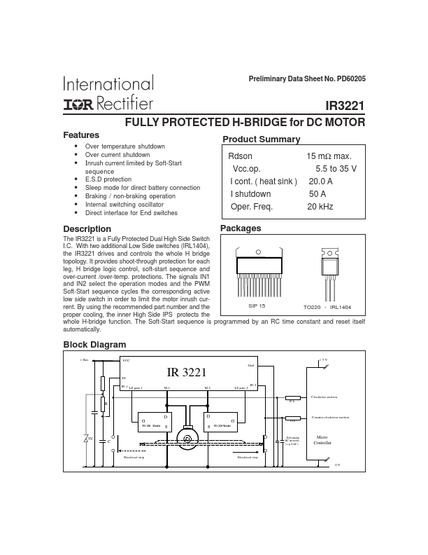
IR3221
Absolute Maximum Ratings
Absolute Maximum Ratings indicate sustained limits beyond which damage to the device may occur. All voltage
parameters are referenced to GROUND pin . T Ambient = 25 °c unless otherwise specified.
Symbol
Vm1(2)
Vin1 (2)
I in1 (2)
Vg1 (2)
Vss
Isd cont.
Isd pulsed
Esd 1
Esd 2
Pd
Tj max.
T lead
Parameter
Maximum M1 (M2) voltage ( active clamp )
Maximum IN 1 (IN 2) voltage
Maximum IN1 (IN 2) current
Maximum Gate 1 ( Gate 2 ) voltage
Maximum SS voltage
Diode max. permanent current (Rth=50°C/W)
Diode max. pulsed current
Electrostatic Disch. (human body model)C=100 pF R= 1500 Ω
Electrostatic Disch. ( Machine model ) C=200 pF R= 0 Ω
Maximum power dissipation (Rth=50°C/W)
Maximum storage & operating junction temperature
Lead temperature ( soldering 10 s )
1
1
1 Limited by junction temperature ( pulsed current limited also by internal wiring
Min.
Vcc-37
-0.3
-1
-0.3
-0.3
-
-
-
-
-
-40
-
Max.
Vcc+0.3
5.5
10
7.5
5.5
4
45
4
0.5
2.5
+150
300
Unit
V
V
mA
V
V
A
A
kV
kV
W
°C
°C
Thermal Characteristics
Symbol
R th 1
R th 2
Parameter
Junction to amb. Thermal resistance
Junction to tab Thermal resistance
typ max Unit
50 - °C/W
1.0 - °C/W
Recommended Operating Conditions
Those values are given for a quick design. For operation outside those conditions, please consult the application note
AN 1032
Symbol
Vcc
Vin1(2)
Vin1(2)
Iout max. 1
Iout max 2
R in
R
C
R gates
Parameter
Continuous Vcc voltage
High level IN1 (IN 2) input voltage
Low level IN1 (IN2) input voltage
Output cont. current ( Rthja=50°C/w, tamb=85°C, Tj=150°C )
Output cont. current ( Rthja=5°C/w, tamb=105°C, Tj=150°C )
Recommended resistor in series with IN pin
Soft-Start resistor
Soft-Start capacitor
Recommended gate resistors for Low Side Switches
2
Min.
8
4
-0.3
-
-
10
5.0
0.1
0
Max.
28
5.5
0.9
7.7
24
20
390
3.3
50
Unit
V
V
V
A
A
kΩ
kΩ
µF
Ω
2 Protections are operating down to 5.5 V
2 www.irf.com