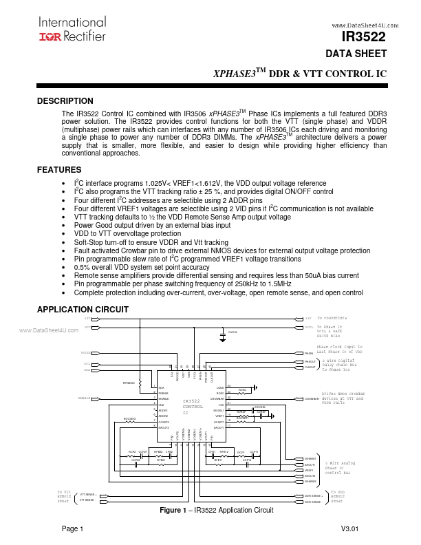
IR3522
ORDERING INFORMATION
Device
IR3522MTRPBF
* IR3522MPBF
Package
32 Lead MLPQ (5 x 5 mm body)
Order Quantity
3000 per reel
100 piece strips
* Samples only
PIN DESCRIPTION
PIN# PIN SYMBOL
1 SDA
2 PGBIAS
3 ENABLE
4 IIN2
5 ADDR1
6 ADDR2
7 OCSET2
www.DataShee8t4U.com EAOUT2
9 FB2
10 VOUT2
11 VOSEN2+
12 VOSEN2-
13 VOSEN1-
14 VOSEN1+
15 VOUT1
16 FB1
17 EAOUT1
18 OCSET1
19 VREF1
20 SS/DEL1
PIN DESCRIPTION
SDA (Serial Data) is a bidirectional signal that is an input and open drain output for
both master (I2C controller) and slave (IR3522). SDA requires a pull resistor to a
bias voltage and should not be floated.
Input to provide bias to the Power Good output transistor directly from the converter
input voltage. Enables the Power Good output to assert even if there is no bias
supplied to the VCCL pin. Internal voltage clamp protects the pin. Do not exceed
100 uA of pull-up current.
Enable input. A logic low applied to this pin puts the IC into fault mode. A logic high
on the pin resets and enables the converter. Do not float this pin as the logic state
will be undefined.
Output 2 average current input from the output 2 phase IC(s).
Digital input to program bit 1 of the 2 bit address code with internal pull-up. Connect
to LGND for logic “0”, float for logic “1”
Digital input to program bit 2 of the 2 bit address code with internal pull-up. Connect
to LGND for logic “0”, float for logic “1”
Programs the output 2 constant converter output current limit through an external
resistor tied to VREF1 and an internal current source from this pin. Over-current
protection can be disabled by over sizing the resistor value to program the threshold
higher than IIN2 pin possible signal amplitude, but no greater than 5V (do not float
this pin as improper operation will occur).
Output of the output 2 error amplifier.
Inverting input to the output 2 error amplifier.
Output 2 remote sense amplifier output.
Output 2 remote sense amplifier input. Connect to output at the load.
Output 2 remote sense amplifier input. Connect to ground at the load.
Output 1 remote sense amplifier input. Connect to ground at the load.
Output 1 remote sense amplifier input. Connect to output at the load.
Output 1 remote sense amplifier output. Provides reference to Error Amp2.
Inverting input to the output 1 error amplifier.
Output of the output 1 error amplifier.
Programs the output 1 constant converter output current limit through an external
resistor tied to VREF1 and an internal current source from this pin. Over-current
protection can be disabled by over sizing the resistor value to program the threshold
higher than IIN2 pin possible signal amplitude, but no greater than 5V (do not float
this pin as improper operation will occur).
Reference voltage programmed by the I2C inputs and error amplifier non-inverting
input. Connect an external RC network to LGND to program dynamic VID slew rate
and provide compensation for the internal buffer amplifier.
Connect an external capacitor to LGND to program startup and Fault delay timing
Page 2
V3.01