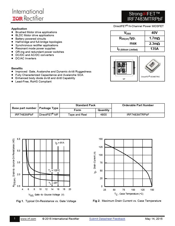
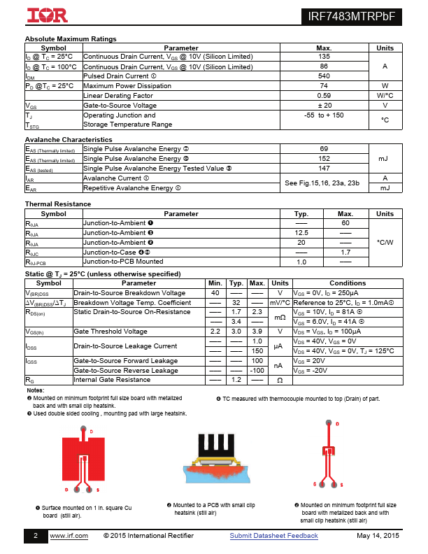
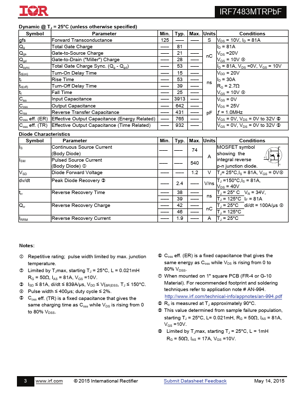
Datasheet4U Logo Datasheet4U.com

IRF7483MTRPbF - Power MOSFET

Key Features

  • ain-to-Source Voltage (V) 100 Fig 10. Maximum Safe Operating Area 0.6 0.5 0.4 0.3 0.2 0.1 0.0 -5 0 5 10 15 20 25 30 35 40 45 VDS, Drain-to-Source Voltage (V) Fig 12. Typical Coss Stored Energy RDS(on), Drain-to -Source On Resistance (m) 10 9 VGS = 5.5V VGS = 6.0V 8 VGS = 7.0V VGS = 8.0V 7 VGS = 10V 6 5 4 3 2 1 0 0 25 50 75 100 125 150 175 200 ID, Drain Current (A) Fig 13. Typical On-Resistance vs. Drain Current 5 www. irf. com © 2015 International Rectifier Submit Datash.

📥 Download Datasheet

Full PDF Text Transcription for IRF7483MTRPbF (Reference)

Note: Below is a high-fidelity text extraction (approx. 800 characters) for IRF7483MTRPbF. For precise diagrams, and layout, please refer to the original PDF.

Application  Brushed Motor drive applications  BLDC Motor drive applications Battery powered circuits  Half-bridge and full-bridge topologies  Synchronous recti...

View more extracted text
ircuits  Half-bridge and full-bridge topologies  Synchronous rectifier applications  Resonant mode power supplies  OR-ing and redundant power switches  DC/DC and AC/DC converters  DC/AC Inverters Benefits  Improved Gate, Avalanche and Dynamic dv/dt Ruggedness  Fully Characterized Capacitance and Avalanche SOA  Enhanced body diode dv/dt and di/dt Capability  Lead-Free, RoHS Compliant StrongIRFET™ IRF7483MTRPbF DirectFET® N-Channel Power MOSFET  VDSS RDS(on) typ. max ID (Silicon Limited) 40V 1.7m 2.