IRFI4110GPBF Overview
| Part | IRFI4110GPBF |
|---|---|
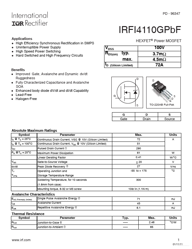
| Description | Power MOSFET |
| Category | MOSFET |
| Manufacturer | International Rectifier |
| Size | 307.01 KB |
| Part Number | Manufacturer | Description |
|---|---|---|
| IRFI4110GPbF | Infineon | Power MOSFET |
| IRFI4110G | Inchange Semiconductor | N-Channel MOSFET |