IRFI4321PBF Overview
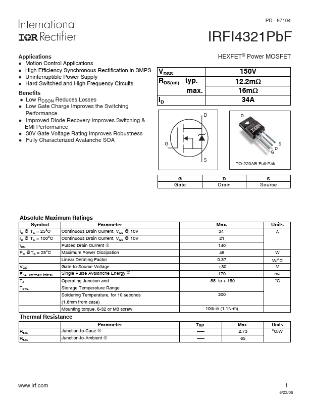
PD - 97104 IRFI4321PbF Applications l Motion Control Applications l High Efficiency Synchronous Rectification in SMPS l Uninterruptible Power Supply l Hard Switched and High Frequency Circuits Benefits l Low RDSON Reduces Losses l Low Gate Charge Improves the Switching Performance l Improved Diode Recovery Improves Switching & EMI Performance l 30V Gate Voltage Rating Improves Robustness l Fully Characterized...
IRFI4321PBF Key Features
- Motion Control Applications
- High Efficiency Synchronous Rectification in SMPS
- Uninterruptible Power Supply
- Hard Switched and High Frequency Circuits Benefits
- Low RDSON Reduces Losses
- Low Gate Charge Improves the Switching Performance
- Improved Diode Recovery Improves Switching & EMI Performance
- 30V Gate Voltage Rating Improves Robustness