MBR3045WT
Overview
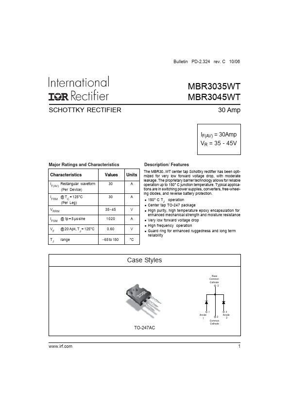
Bulletin PD-2.324 rev. C 10/06 SCHOTTKY RECTIFIER MBR3035WT MBR3045WT 30 Amp IF(AV) = 30Amp VR = 35 - 45V Major Ratings and Characteristics Characteristics IF(AV) Rectangular waveform (Per Device...
| Part | MBR3045WT |
|---|---|
| Description | SCHOTTKY RECTIFIER |
| Manufacturer | International Rectifier |
| Size | 202.51 KB |
Bulletin PD-2.324 rev. C 10/06 SCHOTTKY RECTIFIER MBR3035WT MBR3045WT 30 Amp IF(AV) = 30Amp VR = 35 - 45V Major Ratings and Characteristics Characteristics IF(AV) Rectangular waveform (Per Device...
| Part Number | Manufacturer | Description |
|---|---|---|
| MBR3045WTG | onsemi | Switch Mode Power Rectifier |
| MBR3045WT | Vishay | Schottky Rectifier |
| MBR3045WT | Digitron Semiconductors | 30 A SCHOTTKY RECTIFIERS |
| VS-MBR3045WTPbF | Vishay | High Performance Schottky Rectifier |
| MBR3045WTP | SANGDEST MICROELECTRONICS | SCHOTTKY RECTIFIER |