SK35B
SK35B is SURFACE MOUNT SCHOTTKY BARRIER RECTIFIER manufactured by JQC.
- Part of the SK32B comparator family.
FEATURES
The plastic package carries Underwriters Laboratory Flammability Classification 94V-0 For surface mounted applications Low reverse leakage Built-in strain relief,ideal for automated placement High forward surge current capability High temperature soldering guaranteed: 250 C/10 seconds at terminals
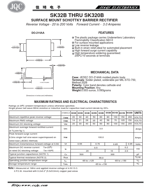
0.096(2.44) 0.084(2.13)
0.060(1.52) 0.030(0.76)
0.008(0.203)MAX. 0.220(5.59) 0.205(5.21)
Dimensions in inches and (millimeters)
MECHANICAL DATA
Case: JEDEC DO-214AA molded plastic body Terminals: Solder plated, solderable per MIL-STD-750, Method 2026 Polarity: Color band denotes cathode end Mounting Position: Any Weight:0.003 ounce, 0.093grams
MAXIMUM RATINGS AND ELECTRICAL CHARACTERISTICS
Ratings at 25 C ambient temperature unless otherwise specified. Single phase half-wave 60Hz,resistive or inductive load,for capacitive load current derate by 20%.
SYMBOLS SK32B SK33B SK34B SK35B SK36B SK38B SK310B SK315B SK320B UNITS
Maximum repetitive peak reverse voltage Maximum RMS voltage Maximum DC blocking voltage Maximum average forward rectified current at TL(see fig.1) Peak forward surge current 8.3ms single half sine-wave superimposed on rated load (JEDEC Method) Maximum instantaneous forward voltage at 3.0A Maximum DC reverse current TA=25 C at rated DC blocking voltage TA=100 C Typical junction capacitance (NOTE 1) Typical thermal resistance (NOTE 2) Operating junction temperature range Storage temperature range
VRRM VRMS VDC I(AV)
IFSM
IR CJ RθJA TJ, TSTG
20 30 40 50 60 80 100 150 200 VOLTS 14 21 28 35 42 56 70 105 150 VOLTS 20 30 40 50 60 80 100 150 200 VOLTS
3.0 Amps
Amps
0.55 0.70
0.5 20
500 -65 to +125
-65 to +150
10 300
0.95 0.2 2.0
-65 to +150
Volts m A p F C/W
Note:1.Measured at 1MHz and applied reverse voltage of 4.0V D.C. 2.P.C.B. mounted with 0.2x0.2”(5.0x5.0mm) copper pad areas
AVERAGE FORWARD RECTIFIED CURRENT, AMPERES
RATINGS AND CHARACTERISTIC CURVES SK32B THRU SK320B
FIG. 1- FORWARD CURRENT DERATING...