RS73F2A Key Features
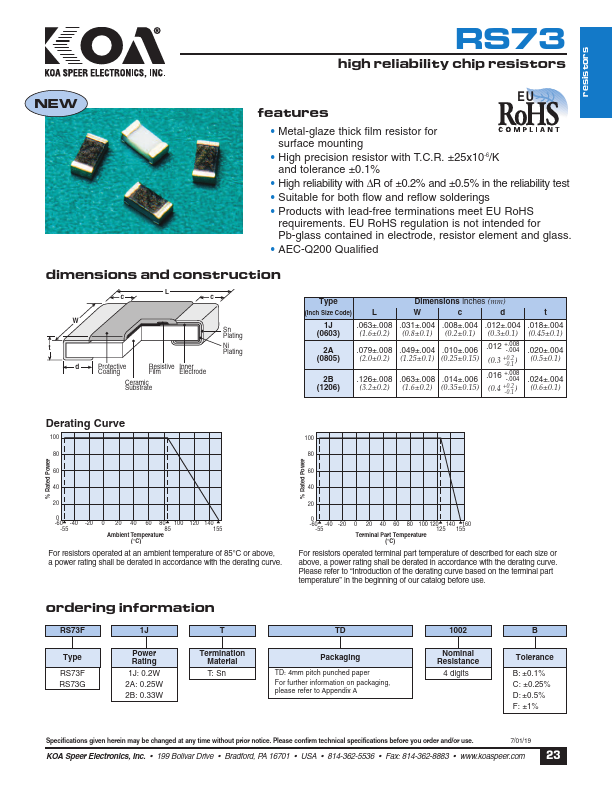
- Metal-glaze thick film resistor for surface mounting
- High precision resistor with T.C.R. ±25x10-6/K and tolerance ±0.1%
- High reliability with ∆R of ±0.2% and ±0.5% in the reliability test
- Suitable for both flow and reflow solderings
- Products with lead-free terminations meet EU RoHS requirements. EU RoHS regulation is not intended for Pb-glass containe
- AEC-Q200 Qualified
- 199 Bolivar Drive
- Bradford, PA 16701
- 814-362-5536
- Fax: 814-362-8883