Datasheet4U Logo Datasheet4U.com

MCR100-8 - Silicon Controlled Rectifier

Download the MCR100-8 datasheet PDF. This datasheet also covers the MCR100-6 variant, as both devices belong to the same silicon controlled rectifier family and are provided as variant models within a single manufacturer datasheet.

Key Features

  • s.
  • Current-IGT : 200 μA.
  • ITRMS : 0.8 A.
  • VRRM/ VDRM : MCR100-6: 400 V MCR100-6R: 400 V MCR100-8: 600 V MCR100-8R: 600 V.
  • Operating and storage junction temperature range.
  • TJ,Tstg : -55℃ to +150℃ 1.70 0.1 0.42 0.1 0.46 0.1.
  • Electrical Characteristics Ta = 25℃ Parameter On State Voltage (Note.1) Gate Trigger Voltage Peak Repetitive forward and MCR100-6/6R rever seblocking voltage MCR100-8/8R Holding current Peak forward or reverse blocking Current Gate.

📥 Download Datasheet

Note: The manufacturer provides a single datasheet file (MCR100-6-Kexin.pdf) that lists specifications for multiple related part numbers.

Full PDF Text Transcription (Reference)

The following content is an automatically extracted verbatim text from the original manufacturer datasheet and is provided for reference purposes only.

View original datasheet text
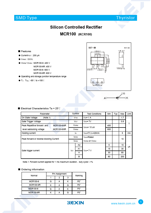
SMD Type Silicon Controlled Rectifier MCR100 (KCR100) Thyristor ■ Features ● Current-IGT : 200 μA ● ITRMS : 0.8 A. ● VRRM/ VDRM : MCR100-6: 400 V MCR100-6R: 400 V MCR100-8: 600 V MCR100-8R: 600 V ● Operating and storage junction temperature range ● TJ,Tstg : -55℃ to +150℃ 1.70 0.1 0.42 0.1 0.46 0.1 ■ Electrical Characteristics Ta = 25℃ Parameter On State Voltage (Note.1) Gate Trigger Voltage Peak Repetitive forward and MCR100-6/6R rever seblocking voltage MCR100-8/8R Holding current Peak forward or reverse blocking Current Gate trigger current Symbol VTM VGT VDRM VRRM IH IDRM IRRM A2 A1 IGT A B Test Conditions ITM= 1 A VAK= 7V IDRM= 10 uA VAK=7V,IH=20mA VAK=Rated VDRM or VRRM VAk= 7 V Note.