Datasheet4U Logo Datasheet4U.com

1N6294A Datasheet TVS Diodes

Manufacturer: Littelfuse

Download the 1N6294A datasheet PDF. This datasheet also includes the 1N6267A variant, as both parts are published together in a single manufacturer document.

📥 Download Datasheet

Note: The manufacturer provides a single datasheet file (1N6267A-Littelfuse.pdf) that lists specifications for multiple related part numbers.

General Description

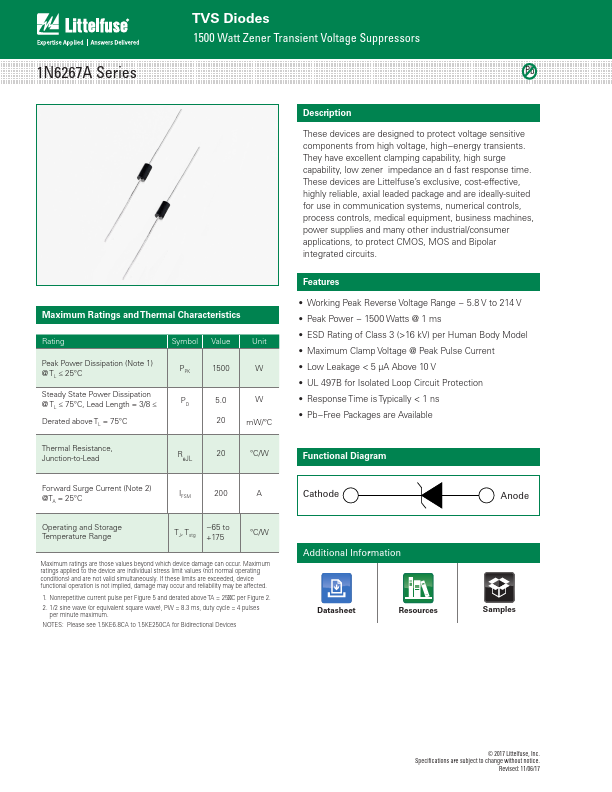
These devices are designed to protect voltage sensitive components from high voltage, high−energy transients.

They have excellent clamping capability, high surge capability, low zener impedance an d fast response time.

These devices are Littelfuse’s exclusive, cost-effective, highly reliable, axial leaded package and are ideally-suited for use in communication systems, numerical controls, process controls, medical equipment, business machines, power supplies and many other industrial/consumer applications, to protect CMOS, MOS and Bipolar integrated circuits.

Overview

1N6267A Series TVS Diodes 1500 Watt Zener Transient Voltage Suppressors Pb Maximum Ratings and Thermal Characteristics Rating Peak Power Dissipation (Note 1) @ TL ≤ 25°C Steady State Power Dissipation @ TL ≤ 75°C, Lead Length = 3/8 ≤ Derated above TL = 75°C Symbol Value PPK 1500 PD 5.0 20 Unit W W mW/°C Thermal Resistance, Junction-to-Lead RθJL 20 °C/W Forward Surge Current (Note 2) @TA = 25°C Operating and Storage Temperature Range IFSM 200 A TJ, Tstg −65 to +175 °C/W Maximum ratings are those values beyond which device damage can occur.

Maximum ratings applied to the device are individual stress limit values (not normal operating conditions) and are not valid simultaneously.

If these limits are exceeded, device functional operation is not implied, damage may occur and reliability may be affected.

Key Features

  • Working Peak Reverse Voltage Range.
  • 5.8 V to 214 V.
  • Peak Power.
  • 1500 Watts @ 1 ms.
  • ESD Rating of Class 3 (>16 kV) per Human Body Model.
  • Maximum Clamp Voltage @ Peak Pulse Current.
  • Low Leakage < 5 µA Above 10 V.
  • UL 497B for Isolated Loop Circuit Protection.
  • Response Time is Typically < 1 ns.
  • Pb.
  • Free Packages areBiA-dvairileacbtlieonal Functional Diagram Cathode Anode Additional Informatio.