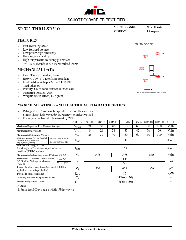
SR502 THRU SR510
SCHOTTKY BARRIER RECTIFIER
VOLTAGE RANGE
CURRENT
20 to 100 Volts
5.0 Ampere
FEATURES
• Fast switching speed
• Low forward voltage
• Low power high efficiency
• High surge capability
• High temperature soldering guaranteed
250℃/10 seconds,0.373”(9.5mm)lead length
MECHANICAL DATA
• Case: Transfer molded plastic
• Epoxy: UL94V-0 rate flame retardant
• Lead: solderarable per MIL-STD-202E
method 208C
• Polarity: Color band denoted cathode end
• Mounting position: Any
• Weight: 0.045 ounce, 1.27 gram
DO-201AD(DO-27)
Dimensions in inches and (millimeters)
MAXIMUM RATINGS AND ELECTRICAL CHARACTERISTICS
• Ratings at 25℃ ambient temperature unless otherwise specified
• Single Phase, half wave, 60Hz, resistive or inductive load
• For capacitive load derate current by 20%
SYMBOLS SR502 SR503
Maximum Repetitive Peak Reverse Voltage
Maximum RMS Voltage
Maximum DC Blocking Voltage
Maximum Average Forward Rectified
Current,0.375”(9.5mm)Lead
length,(Note 1)See Fig.1
TL = 60℃(SR502-504)
TL = 85℃(SR505-510)
Peak Forward Surge Current
8.3mS single half sine-wave superimposed on
rated load (JEDEC method)
VRRM
VRMS
VDC
I(AV)
IFSM
20
14
20
30
21
30
Maximum Instantaneous Forward Voltage @ 5.0A
Maximum DC Reverse Current at rated TA = 25℃
DC Blocking Voltage per element
(Note 1)
TA = 100℃
Typical Junction Capacitance(Measured at 1.0Hzand
applied reverse voltage of 4.0V)
VF
IR
CJ
0.55
550
Typical Thermal Resistance
RθJA
Operating Junction Temperature Range
TJ
Storage Temperature Range
TSTG
Notes:
1. Pulse test:300μs pulse width,1%duty cycle
SR504
40
28
40
SR505
50
35
50
SR506 SR508 SR510
60 80 100
42 56 70
60 80 100
5.0
150
0.75
1.0
50
450
15
(-55 to +150)
(-55 to +150)
0.85
350
UNIT
Volts
Volts
Volts
Amps
Amps
Volts
mA
pF
℃/W
℃
℃
Web Site: www.hkmic.com