MOSPEC
Schottky Barrier Rectifiers
Using the Schottky Barrier principle with a Molybdenum barrier metal. These
state-of-the-art geometry features 
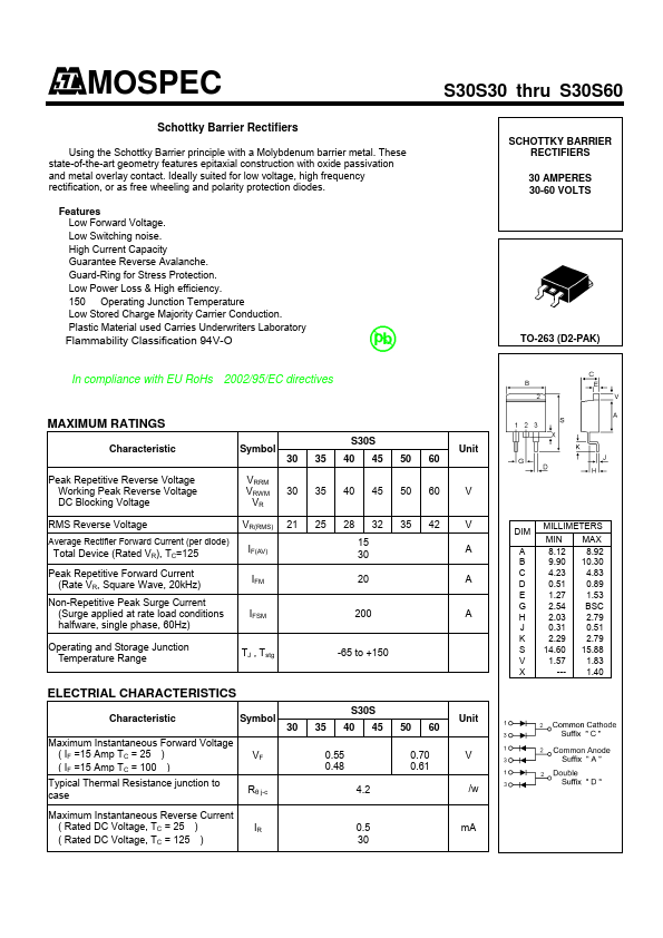
epitaxial construction with oxide passivation
and metal overlay contact. Ideally suited for low voltage, high frequency
rectification, or as free wheeling and polarity protection diodes.
Features
Low Forward Voltage.
Low Switching noise.
High Current Capacity
Guarantee Reverse Avalanche.
Guard-Ring for Stress Protection.
Low Power Loss & High efficiency.
150 Operating Junction Temperature
Low Stored Charge Majority Carrier Conduction.
Plastic Material used Carries Underwriters Laboratory
Flammability Classification 94V-O
In compliance with EU RoHs 2002/95/EC directives
S30S30 thru S30S60
SCHOTTKY BARRIER
RECTIFIERS
30 AMPERES
30-60 VOLTS
TO-263 (D2-PAK)
MAXIMUM RATINGS
Characteristic
Symbol
S30S
Unit
30 35 40 45 50 60
Peak Repetitive Reverse Voltage
Working Peak Reverse Voltage
DC Blocking Voltage
VRRM
VRWM 30 35 40 45 50 60
VR
V
RMS Reverse Voltage
VR(RMS) 21 25 28 32 35 42
Average Rectifier Forward Current (per diode)
Total Device (Rated VR), TC=125
IF(AV)
15
30
Peak Repetitive Forward Current
(Rate VR, Square Wave, 20kHz)
Non-Repetitive Peak Surge Current
(Surge applied at rate load conditions
halfware, single phase, 60Hz)
IFM
IFSM
20
200
V
A
A
A
Operating and Storage Junction
Temperature Range
TJ , Tstg
-65 to +150
ELECTRIAL CHARACTERISTICS
Characteristic
Symbol
Maximum Instantaneous Forward Voltage
( IF =15 Amp TC = 25 )
( IF =15 Amp TC = 100 )
Typical Thermal Resistance junction to
case
VF
Rθ j-c
30
Maximum Instantaneous Reverse Current
( Rated DC Voltage, TC = 25 )
( Rated DC Voltage, TC = 125 )
IR
S30S
35 40 45
0.55
0.48
4.2
0.5
30
50 60
0.70
0.61
Unit
V
/w
mA
DIM
MILLIMETERS
MIN MAX
A 8.12 8.92
B 9.90 10.30
C 4.23 4.83
D 0.51 0.89
E 1.27 1.53
G 2.54 BSC
H 2.03 2.79
J 0.31 0.51
K 2.29 2.79
S 14.60 15.88
V 1.57 1.83
X --- 1.40