SRF1060C Overview
Key Specifications
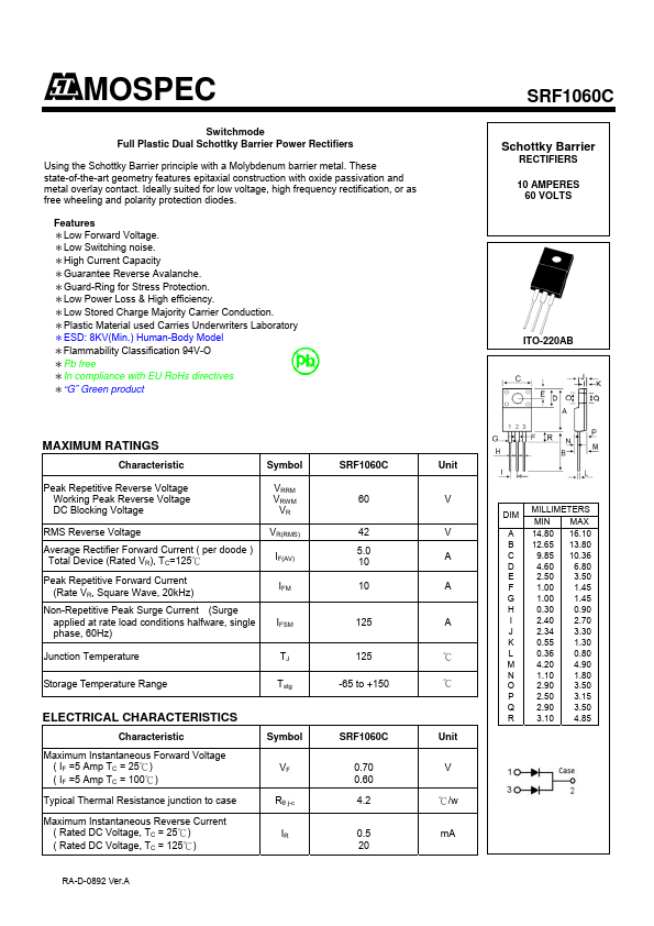
Pins: 3
Max Operating Temp: 150 °C
Min Operating Temp: -55 °C
Key Features
- epitaxial construction with oxide passivation and metal overlay contact
- Ideally suited for low voltage, high frequency rectification, or as free wheeling and polarity protection diodes
- Features *Low Forward Voltage
- *Low Switching noise
- *High Current Capacity *Guarantee Reverse Avalanche