URAF0560
| Part | URAF0560 |
|---|---|
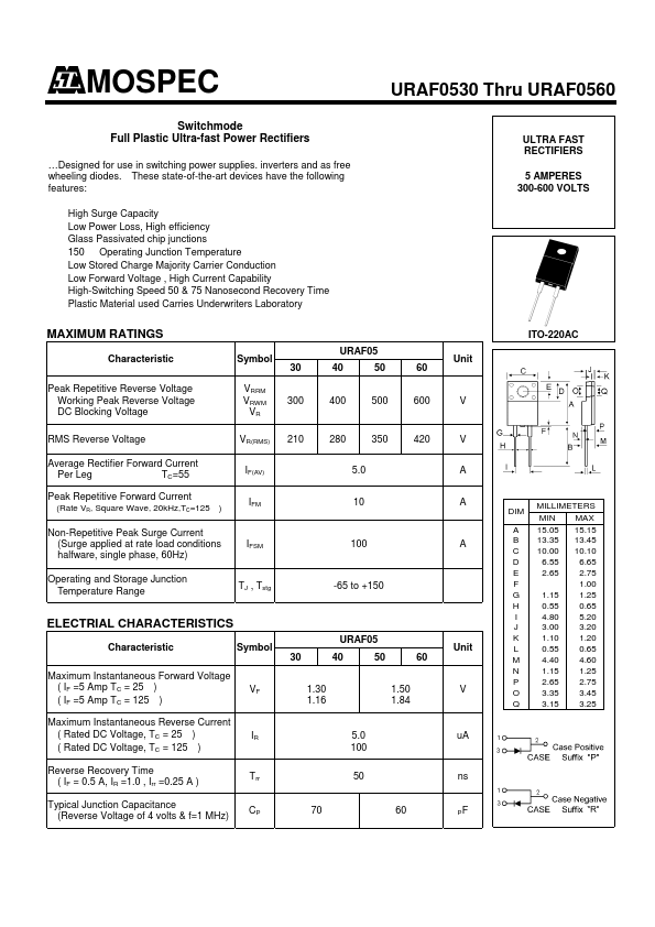
| Description | Ultra-fast Power Rectifiers |
| Manufacturer | Mospec Semiconductor |
| Size | 252.61 KB |
| Part Number | Manufacturer | Description |
|---|---|---|
| B3045G | onsemi | Switch-mode Power Rectifiers |
| 1N4007 | Fairchild Semiconductor | General Purpose Rectifiers |
| 1N4007 | onsemi | Axial Lead Standard Recovery Rectifiers |