MAX2014 Overview
Key Specifications
Package: UMAX
Mount Type: Surface Mount
Pins: 8
Max Voltage (typical range): 5.25 V
Description
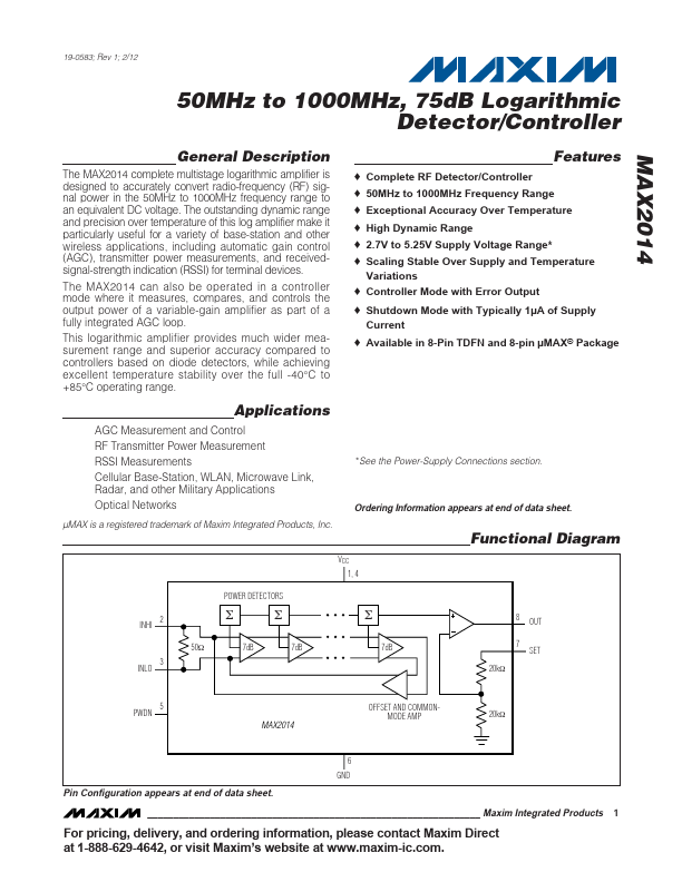
The MAX2014 complete multistage logarithmic amplifier is designed to accurately convert radio-frequency (RF) signal power in the 50MHz to 1000MHz frequency range to an equivalent DC voltage. The outstanding dynamic range and precision over temperature of this log amplifier make it particularly useful for a variety of base-station and other wireless applications, including automatic gain control (AGC), transmitter power measurements, and receivedsignal-strength indication (RSSI) for terminal devices.